527
Memory Areas Appendix C
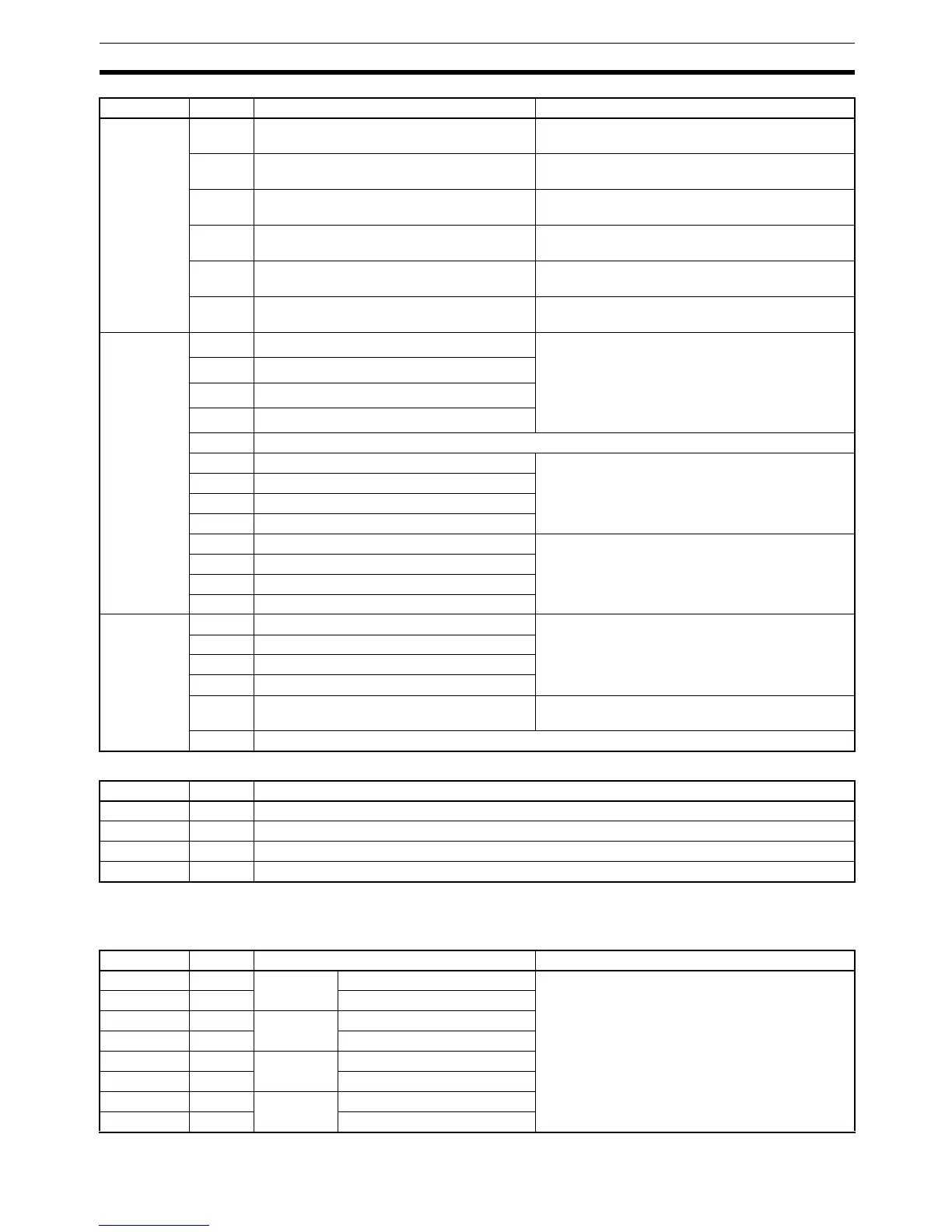
Analog Setting Board (Slot 1 and 2) Flags/Bits
Flags/Bits for an Inner Board in Slot 2 (IR 232 to IR 243)
High-speed Counter Board Flags/Bits
IR 208
(High-speed
counter 1)
IR 209
(High-speed
counter 2)
IR 210
(High-speed
counter 3)
IR 211
(High-speed
counter 4)
00 to 07 Comparison Results: Internal Output Bits Contains the bit pattern specified by operand in
CTBL(––) when conditions are satisfied.
08 to 11 Comparison Results: External Output Bits
for Outputs 1 to 4
Contains the bit pattern specified by operand in
CTBL(––) when conditions are satisfied.
12 Counter Operating Flag 0: Stopped
1: Operating
13 Comparison Flag Indicates whether comparison is in progress.
0: Stopped; 1: Operating
14 PV Overflow/Underflow Flag 0: Normal
1: Overflow or underflow occurred.
15 SV Error Flag 0: Normal
1: SV error occurred.
IR 212 00 High-speed Counter 1 Reset Bit Phase Z and software reset
0: Counter not reset on phase Z
1: Counter reset on phase Z
Software reset only
0: Counter not reset
0→1: Counter reset
01 High-speed Counter 2 Reset Bit
02 High-speed Counter 3 Reset Bit
03 High-speed Counter 4 Reset Bit
04 to 07 Not used.
08 High-speed Counter 1 Comparison Stop Bit 0→1: Starts comparison.
1→0: Stops comparison.
09 High-speed Counter 2 Comparison Stop Bit
10 High-speed Counter 3 Comparison Stop Bit
11 High-speed Counter 4 Comparison Stop Bit
12 High-speed Counter 1 Stop Bit 0: Continues operation.
1: Stops operation.
13 High-speed Counter 2 Stop Bit
14 High-speed Counter 3 Stop Bit
15 High-speed Counter 4 Stop Bit
IR 213 00 External Output 1 Force-set Bit 0: No effect on output status
1: Forces output ON
01 External Output 2 Force-set Bit
02 External Output 3 Force-set Bit
03 External Output 4 Force-set Bit
04 External Output Force-set Enable Bit 1: Force-setting of outputs 1 to 4 enabled
0: Force-setting of outputs 1 to 4 disabled
05 to 15 Not used.
Word Bits Function
IR 220 00 to 15 Analog SV 1: 0000 to 0200 (4-digit BCD)
IR 221 00 to 15 Analog SV 2: 0000 to 0200 (4-digit BCD)
IR 222 00 to 15 Analog SV 3: 0000 to 0200 (4-digit BCD)
IR 223 00 to 15 Analog SV 4: 0000 to 0200 (4-digit BCD)
Word Bits Name Function
IR 232 00 to 15 High-speed
Counter 1
PV (rightmost 4 digits) Contains the high-speed counter PV for each of
the High-speed Counter Board’s ports.
Note The PV data format (BCD or hexadecimal)
can be set in the PC Setup (DM 6602.)
IR 233 00 to 15 PV (leftmost 4 digits)
IR 234 00 to 15 High-speed
Counter 2
PV (rightmost 4 digits)
IR 235 00 to 15 PV (leftmost 4 digits)
IR 236 00 to 15 High-speed
Counter 3
PV (rightmost 4 digits)
IR 237 00 to 15 PV (leftmost 4 digits)
IR 238 00 to 15 High-speed
Counter 4
PV (rightmost 4 digits)
IR 239 00 to 15 PV (leftmost 4 digits)
Word Bits Name Function