56
Communications Functions Section 1-6
Note The peripheral port cannot be used for 1:1 Data Links. Use the CPU Unit’s
built-in RS-232C port or a Serial Communications Board’s RS-232C or RS-
422A/485 port.
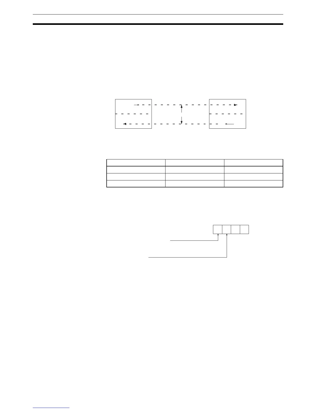
One-to-one Data Links A 1:1 Data Link allows two CQM1Hs to share common data in their LR areas.
As shown in the diagram below, when data is written into a word the LR area
of one of the linked Units, it will automatically be written identically into the
same word of the other Unit. Each PC has specified words to which it can
write and specified words that are written to by the other PC. Each can read,
but cannot write, the words written by the other PC.
The word used by each PC will be as shown in the following table, according
to the settings for the master, slave, and link words. Set the link area to LR 00
to LR 15 if the CQM1H is being linked with a CPM1, CPM1A, CPM2A, or
SRM1(-V2) PC.
PC Setup Settings To use a 1:1 Data Link, the only settings necessary are the communications
mode and the link words. Set the communications mode for one of the PCs to
the 1:1 Data Link Master and the other to the 1:1 Data Link Slave, and then
set the link words in the PC designated as the master.
Note These settings are valid only when pin 5 of the CPU Unit’s DIP Switch is OFF.
Bits 08 to 11 are valid only in the 1:1 Data Link Master.
Communications
Procedure
If the settings for the master and the slave are made correctly, then the One-
to-one Data Link will be automatically started up simply by turning on the
power supply to both of the CPU Units and operation will be independent of
the CPU Units’ operating modes.
Link Errors If a slave does not received a response from the master within one second,
the 1:1 Data Link Error Flag (AR 0802) and the Communications Error Flag
(AR 0804) will be turned ON.
Application Example This example shows a program for verifying the conditions for executing a
One-to-one Data Link using the RS-232C ports. Before executing the pro-
gram, set the following PC Setup parameters.
1
11
Master Slave
Master area
Slave area
Written automatically.
Write "1"
Master area
Slave areaWrite
DM 6645 setting Master area Slave area
LR 00 to LR 15 LR 00 to LR 07 LR 08 to LR 15
LR 00 to LR 31 LR 00 to LR 15 LR 16 to LR 31
LR 00 to LR 63 LR 00 to LR 31 LR 32 to LR 63
15 0
Bit
0 0
Communications mode
2: One-to-one data link slave
3: One-to-one data link master
Link words
0: LR 00 to LR 63
1: LR 00 to LR 31
2: LR 00 to LR 15
Default: Communications mode = 0 (Host Link)
DM 6645