EasyManua.ls Logo

Omron TJ1-MC04 - PROGRAMMING 1 User Manual

Omron TJ1-MC04 - PROGRAMMING 1
312 pages
To Next Page IconTo Next Page
To Previous Page IconTo Previous Page
Page #36 background imageLoading...
Page #36 background image
BASIC commands
PROGRAMMING MANUAL 36
Revision 3.0
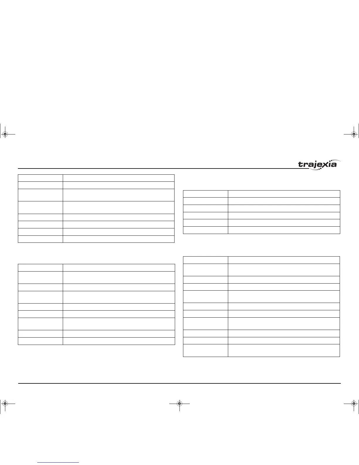
3.1.3 Communication commands and parameters
/i
3.1.4 Constants
/i
3.1.5 I/O commands, functions and parameters
/i
SRAMP Contains the S-curve factor.
T_REF Contains the torque reference value which is applied to the
servo motor.
TRANS_DPOS Contains axis demand position at output of frame transforma-
tion.
UNITS Contains the unit conversion factor.
VERIFY Selects different modes of operation on a stepper output axis.
VFF_GAIN Contains the speed feed forward control gain.
VP_SPEED Contains the speed profile speed.
Name Description
FINS_COMMS Sends FINS Read Memory and Write Memory to a designated
FINS server unit.
HLM_COMMAND Executes a specific Host Link command to the Slave.
HLM_READ Reads data from the Host Link Slave to either VR or TABLE var-
iable array.
HLM_STATUS Represents the status of the last Host Link Master command.
HLM_TIMEOUT Defines the Host Link Master timeout time.
HLM_WRITE Writes data to the Host Link Slave from either VR or TABLE var-
iable array.
HLS_NODE Defines the Slave unit number for the Host Link Slave protocol.
SETCOM Sets the serial communications.
Name Description
Name Description
FALSE Equal to the numerical value 0.
OFF Equal to the numerical value 0.
ON Equal to the numerical value 1.
PI Equal to the numerical value 3.1416.
TRUE Equal to the numerical value -1.
Name Description
GET Waits for the arrival of a single character and assigns the ASCII
code of the character to variable.
IN Returns the value of digital inputs.
INDEVICE Parameter defines the default input device.
INPUT Waits for a string to be received and assigns the numerical value
to variable.
KEY Returns TRUE or FALSE depending on if character is received.
LINPUT Waits for a string and puts it in VR variables.
OP Sets one or more outputs or returns the state of the first 24 out-
puts.
OUTDEVICE Defines the default output device.
PRINT Outputs a series of characters to a serial port.
PSWITCH Turns on an output when a predefined position is reached, and
turns off the output when a second position is reached.
I52E-EN-03.book Seite 36 Freitag, 29. Juni 2007 11:55 11

Table of Contents

Questions and Answers:

Omron TJ1-MC04 - PROGRAMMING 1 Specifications

General IconGeneral
BrandOmron
ModelTJ1-MC04 - PROGRAMMING 1
CategoryController
LanguageEnglish

Summary

Notice and Trademarks

Definition of Precautionary Information

Defines DANGER, WARNING, and CAUTION symbols used for safety precautions.

Trademarks and Copyrights

Lists trademarks and copyright information related to the product and manual.

About this Manual

Trajexia Motion Control System QUICK START GUIDE

Describes how to quickly get familiar with Trajexia, moving a single axis using MECHATROLINK-II.

Trajexia Motion Control System PROGRAMMING MANUAL

Details BASIC commands, communication protocols, Trajexia Tools, examples, and troubleshooting.

Functions Supported by Unit Versions

Verify Firmware and FPGA Versions

Instructions to verify firmware and FPGA versions of the TJ1-MC__ using Trajexia Tools.

Safety Warnings and Precautions

1.1 Intended Audience

Specifies the target audience for the manual: personnel knowledgeable in electrical systems.

1.2 General Precautions

Outlines general operating precautions and consultation requirements for specific applications.

1.3 Safety Precautions

Details critical safety measures for handling units, internal parts, and avoiding electrical shock.

1.4 Operating Environment Precautions

Lists precautions for operating the unit in specific environmental conditions to prevent malfunction.

1.5 Application Precautions

Covers precautions for system operation, program checks, power supply, and external wiring.

1.6 Unit Assembly Precautions

Provides precautions for proper unit installation and termination unit mounting.

Trajexia System Overview

2.1 Introduction

Introduces Trajexia as a flexible motion platform with DSP-powered coordination.

2.1.1 Trajexia Hardware

Details Trajexia hardware components: Ethernet, Serial Port, MECHATROLINK-II, and drives.

2.3 BASIC Programming

Introduces BASIC language structure: commands, functions, parameters, and statements.

2.4 Motion Execution

Explains motion execution, including the motion generator, sequencing, and move loading processes.

2.5 Command Line Interface

Describes the command line interface for executing commands and accessing system parameters.

2.6 BASIC Programs

Covers managing BASIC programs: storage, manipulation, and Trajexia Tools integration.

BASIC Commands Reference

3.1 Categories

Lists categories of BASIC commands: Axis, Communication, I/O, Mathematical, System, Task.

3.1.1 Axis Commands

Provides a reference for axis commands like ACC, ADDAX, BASE, CAM, CANCEL, CONNECT.

3.1.2 Axis Parameters

Lists key axis parameters such as ACCEL, ATYPE, AXISSTATUS, DPOS, SERVO, SPEED.

3.1.3 Communication Commands and Parameters

Details communication commands and parameters like FINS_COMMS, HLM_READ, SETCOM.

3.1.5 I/O Commands, Functions and Parameters

Lists I/O commands, functions, and parameters such as GET, IN, OP, PRINT, PSWITCH.

3.1.6 Mathematical Functions and Operands

Covers mathematical functions and operands including ABS, AND, COS, EXP, INT, SIN, SQR.

3.1.8 Program Control Commands

Lists program control commands like DEL, DIR, RUN, STOP, STEPLINE, TRON.

3.2 All BASIC Commands (Selected)

Highlights key BASIC commands: +, BASE, CONNECT, MOVE, RUN, TABLE, UNITS.

Communication Protocols

4.1 Available Interfaces

Lists available interfaces: Ethernet, Serial, PROFIBUS, DeviceNet, MECHATROLINK-II.

4.2 Ethernet

Describes Ethernet port configuration: IP address, subnet mask, and gateway settings.

4.2.1 Communicate Directly from Computer

Instructions for direct PC-Trajexia connection via Ethernet, including settings.

4.2.2 Communicate Remotely

Explains remote connection to Trajexia system via Ethernet, covering IP settings.

4.2.4 FINS Server Protocol

Details the FINS protocol for communication with OMRON devices and its implementation.

4.3 Serial Protocol

Describes TJ1-MC__ serial ports and supported protocols: Host Link and User-defined.

4.3.1 Host Link Master

Explains sending BASIC commands to a Host Link slave when TJ1-MC__ is master.

4.3.2 Host Link Slave

Details how a master reads/writes data to TJ1-MC__ when it acts as a slave.

4.4 PROFIBUS

Introduces PROFIBUS standard and communication setup for TJ1-PRT.

4.5 DeviceNet

Introduces DeviceNet standard and communication setup for TJ1-DRT.

4.6 MECHATROLINK-II

Describes MECHATROLINK-II protocol for deterministic motion control and its cyclic transmission.

Trajexia Tools Interface

5.1 Introduction

Introduces Trajexia Tools software for programming, monitoring, and debugging the Trajexia system.

5.2 Specifications and Connections

Lists PC specifications and connection procedures for Trajexia Tools.

5.3 Projects

Explains Trajexia Tools Projects for easier application design, consistency, and backup.

5.4 Trajexia Tools Application Window

Details the components of the Trajexia Tools window: Control Panel, Menu Bar, Toolbar.

5.5 Menu Descriptions

Describes Project, Controller, Program, Tools, Options, Windows, and Help menus.

Examples and Tips

6.1 How-to’s

Provides guidance on specific tasks: Startup program, Gain settings, UNITS parameter, Mapping I/O.

6.1.5 Origin Search

Explains the origin search (homing) functionality and its pre-defined sequences.

6.1.6 Registration

Explains registration for real-time axis position storing upon external input activation.

6.1.7 Tracing and Monitoring

Details oscilloscope functionality for tracing axis/system parameters for development and troubleshooting.

6.2 Practical Examples

Presents practical examples: Shell program, Initialization, Single axis, Product detection, Grid positioning.

6.2.1 Shell Program

Explains the importance and structure of a shell program for application management.

6.2.2 Initialization Program

Describes setting axis parameters based on encoder resolution and motor speed.

6.2.3 Single Axis Program

Provides a simple BASIC program example for running a single axis.

6.2.4 Position with Product Detection

Describes a ballscrew moving to detect a product using a microswitch.

6.2.5 Position on a Grid

Describes positioning on a grid for filling boxes on a palette.

6.2.6 Bag Feeder Program

Explains bag feeder operation modes and provides a typical program code.

6.2.7 CAM Table Inside a Program

Shows how to create a CAM table and use the CAMBOX command.

6.2.8 Flying Shear Program

Provides an example of a Flying shear program involving three axes.

6.2.9 Correction Program

Describes a correction program for a rotary labeller using a virtual axis.

Troubleshooting

7.1 Voltage and Analysis Tools

Advises checking power supply voltage and using Trajexia Tools for diagnosis.

7.2 TJ1-MC__

Covers system, axis, unit, and configuration errors for the TJ1-MC__.

7.2.1 System Errors

Explains system errors shown on TJ1-MC__ LED and lists common errors with causes/solutions.

7.2.2 Axis Errors

Explains axis errors, their causes (parameter, Servo Driver), and removal steps.

7.2.3 Unit Errors

Details unit errors, their causes (defective unit, disconnection), and solutions.

7.2.4 Configuration Errors

Lists causes of configuration errors and how to solve them by adhering to system unit rules.

7.2.5 Replace the Battery

Provides steps for replacing the unit's backup battery to prevent data loss.

7.3 TJ1-PRT

Covers system errors and I/O communication problems for the TJ1-PRT.

7.4 TJ1-DRT

Covers system errors and I/O communication problems for the TJ1-DRT.

7.5 TJ1-ML__

Covers system errors and bus errors for the TJ1-ML__.

7.6 TJ1-FL02

Covers system errors for the TJ1-FL02.

Revision History

Related product manuals