Manual Version e1-4.3.0.ae-R3. Page
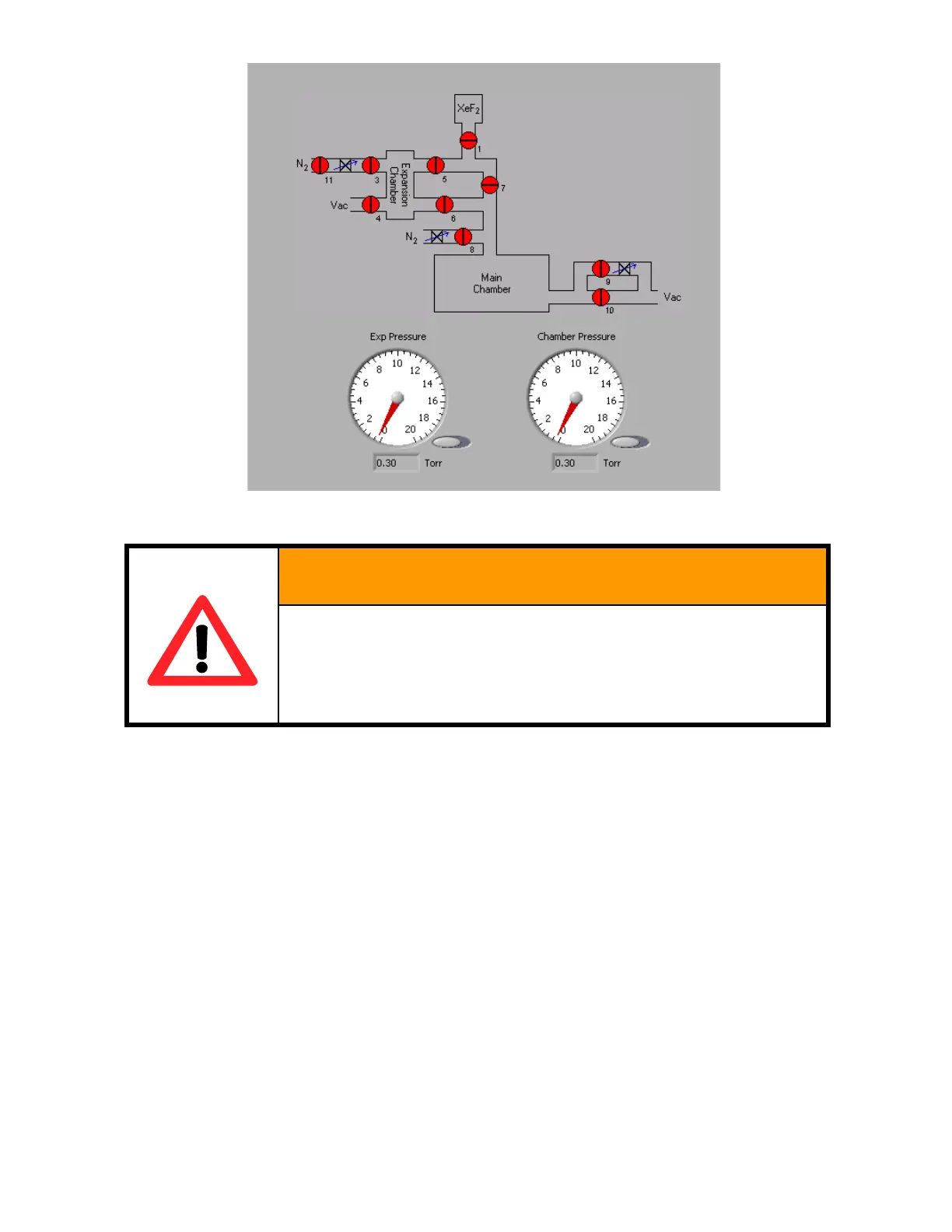
Figure 50. Valve diagram.
MANUAL OPERATION OF THE VALVES COULD LEA
DAMAGE TO THE EQUIPMENT OR HARM TO PERSO
MANUAL VALVE OPERATION IS INDEPENDENT OF
INTERLOCKS AND SHOULD ONLY BE PERFORMED BY
In service or maintenance circumstances, only to be performed using trained personnel, where manual
operation of the valves is necessary, manual valve operation can be accomplished using a small allen
wrench or other small, pointed object. The valve manifold, see Figure 49, has 16 buttons that can be
pressed to force a valve to open. For reference, the valve diagram for the system is shown in Figure
50.
6.15 Ventilation shroud interlock
The ventilation shroud is interlocked via a safety switch/lock mechanism as shown in Figure 51. This
mechanism is controlled via the PC and the input/output signals related to this interlock are
communicated through the device shown in Figure 52.
If it is necessary to override the Ventilation shroud interlock, a pair of keys is provided that are used to
unlock the shroud.