Manual Version e1-4.3.0.ae-R3. Page
6.2.3 Panel Layouts
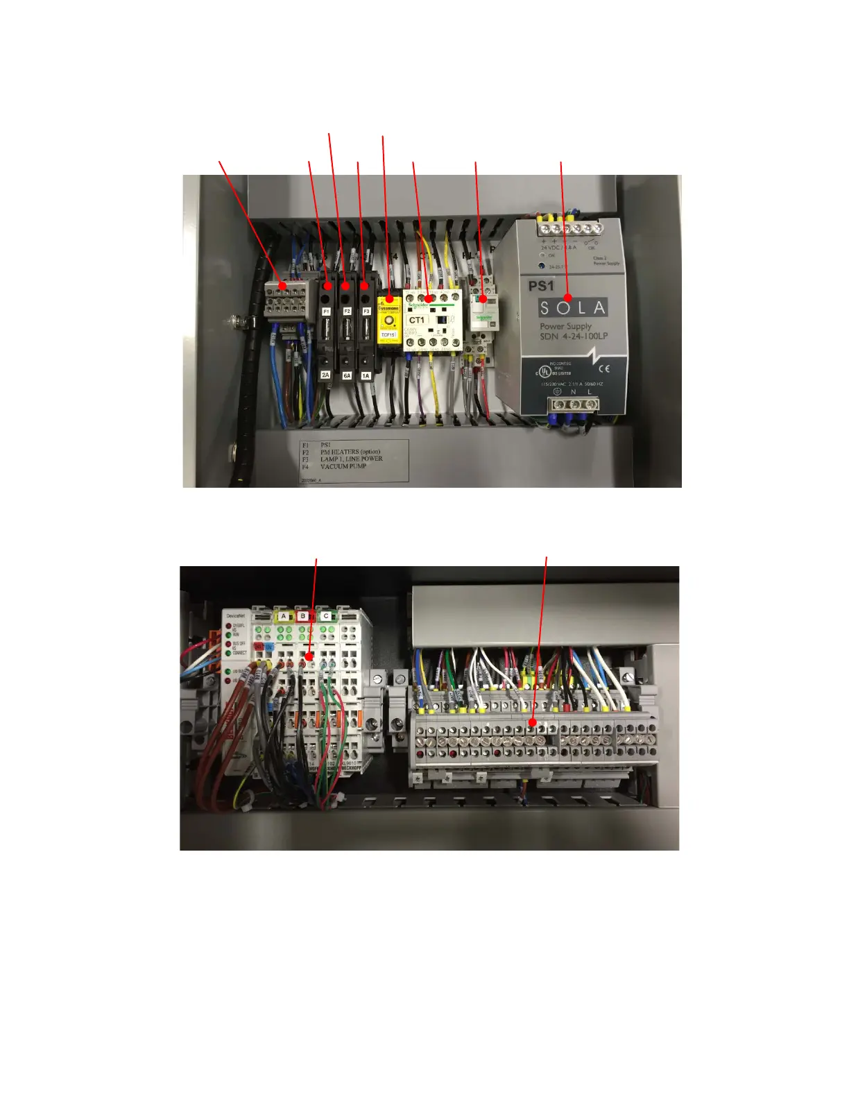
The panel layouts of the electrical power box (remote unit) and internal electrical units are shown in
Figure 36 and Figure 37, respectively.
Figure 36. Remote box panel layout.
Figure 37. Internal panel layout.
6.3 Turning on the System after Maintenance
If the system was unplugged and locked out restore power to the system by plugging it back in to the
electrical outlet. If the pressurized gasses were turned off, turn them back on at the customer supplied
regulator assuring that the supply pressures do not exceed those listed in section 4.1.6. Follow the
procedures in section 4.7 to start the system.
DC Terminal Blocks and DeviceNet