Wiring FP0
7 − 6
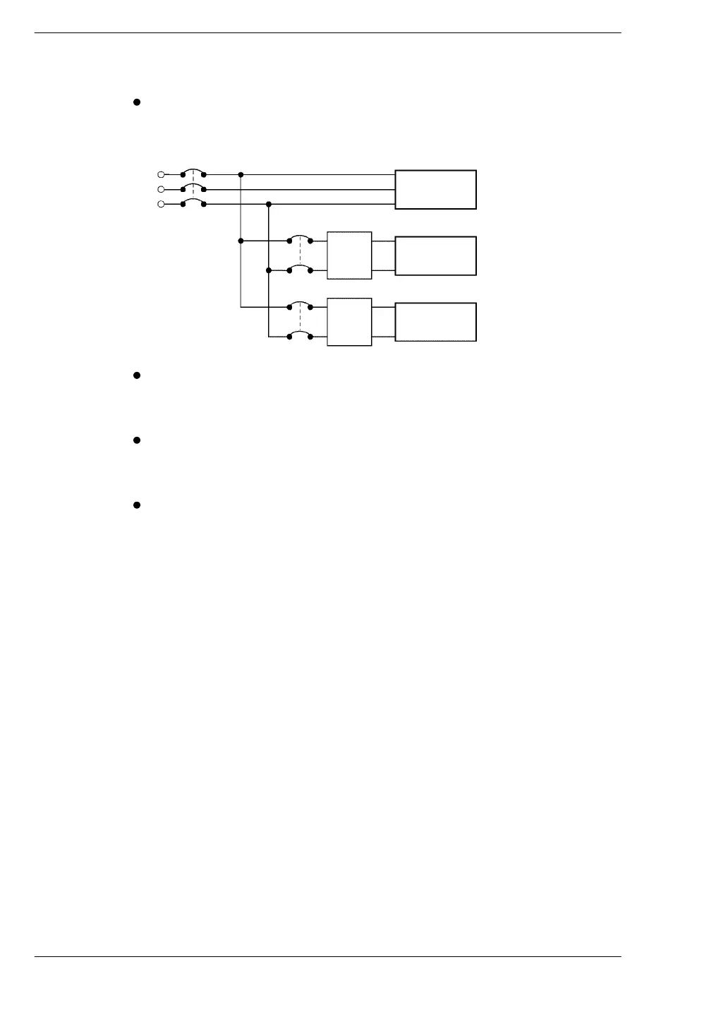
7.2 Wiring the Power Supply to the Control Unit
Isolate the wiring systems to the FP0, input/output devices,
and motor devices.
FP0
I/O
devices
Motor
devices
Circuit breaker
Insulated
DC
power
supply
Insulated
DC
power
supply
The power supply sequence should be set up so that power to
the control unit is turned OFF before the input/output power
supplies.
If the input/output power supplies are turned OFF before the
power to the control unit, the FP0 control unit may detect a
drop in the input level, and malfunction.
Be sure to supply power to a control unit and an expansion
unit from the same power supply, and turn the power ON and
OFF simultaneously for both.