Optional Memory FP0
2 − 6
2.1 Parts and Terminology
2.1.1.1 Status Indicator LEDs
These LEDs display the current mode of operation or the occurrence of an error.
LED Description
RUN (green) Illuminates when in the RUN mode and indicates the execution of a program. It flashes during
forced input/output.
PROG. (green) Illuminates when in the PROG. mode and indicates that operation has stopped.
ERROR/ALARM
(red)
Flashes when an error is detected during the self-diagnostic function. Illuminates if a hard-
ware error occurs, or if operation slows because of the program, and the watchdog timer is
activated.
2.1.1.2 Mode Switch
This switch turns ON and OFF (RUN/PROG.) the operation of the FP0. The FP0 can
also be turned ON and OFF by the programming tool.
Switch position Operation mode
RUN (upward) This sets the RUN mode. The program is executed and operation begins.
PROG. (downward) This sets the PROG. mode.
When performing remote switching from the programming tool, the position of the mode
switch and the actual mode of operation may differ. Verify the mode with the status
indicator LED. Otherwise, restart the FP0 and change the mode of operation with the
mode switch.
2.1.1.3
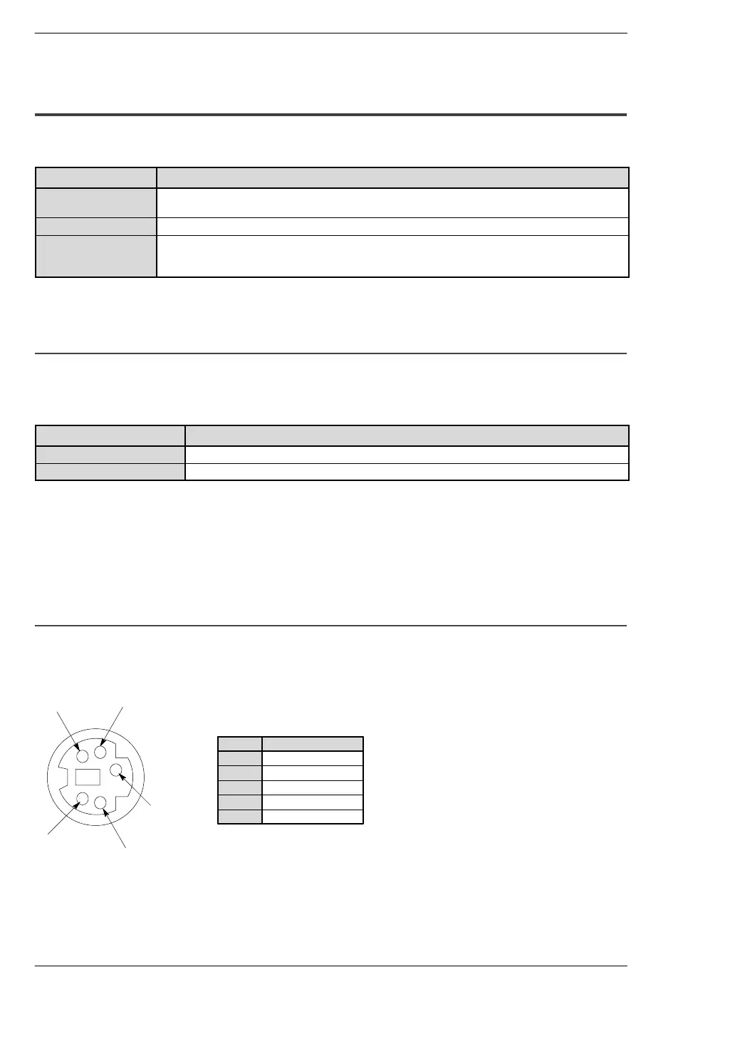
Tool Port
The tool port is used to connect a programming tool.
Pin assignment
3
4
5
1
2
Abbreviation
SG
SD (TXD)
RD (RXD)
+5V
—
Pin no.
3
2
4
1
5