S−LINK Control UnitFP0
4 − 7
4.3 Wiring the Power Supply
4.3 Wiring the Power Supply
With the FP0 S−LINK control unit, power must be supplied at two locations (power
supply connector and S−LINK terminal block).
4.3.1 Wiring to Power Supply Connector
This is the power supply for the programmable controller section and the S−LINK
controller in the S−LINK control unit (24V DC, 150mA).
Power
supply
cable
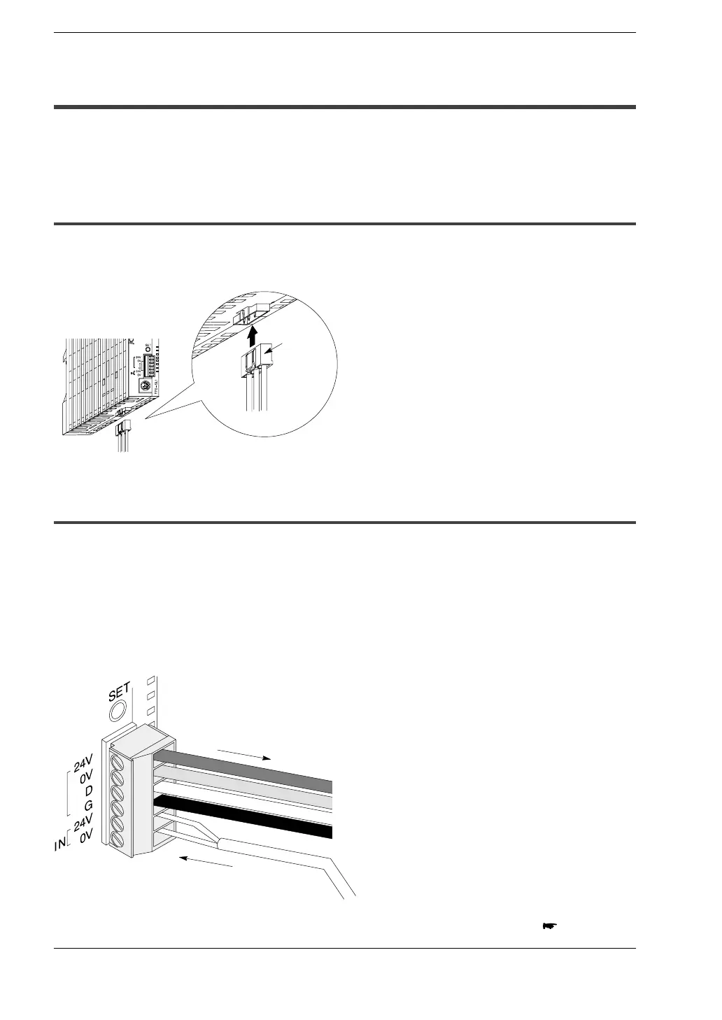
4.3.2 Wiring to S−LINK Terminal Block
This is the power supply for the S−LINK controller in the S−LINK control unit and other
S−LINK input/output devices to which power is supplied through the 24V − 0V line of
the S−LINK main cable.
The current consumption for the overall S−LINK system is calculated by referring to the
section entitled “Determining the Power Supply” in the “S−LINK Design Manual.” (For
standard purposes, a power supply exceeding 24V DC, 1.6 A should be selected.)
0V
+24V
From external
power supply
Supplied to S−LINK
input/output devices
Brown
Blue
White
Black
Supply of power to S−LINK terminal block
next page