Optional Memory FP0
2 − 14
2.2 Specifications
2.2.3 Input Specifications
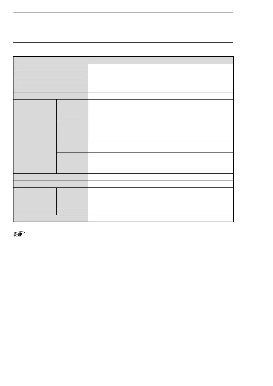
Item Description
Insulation method optical coupler
Rated input voltage 24 V DC
Rated input current approx. 4.3 mA (at 24 V DC)
Input impedance approx. 5.6 kΩ
Operating voltage range 21.6 to 26.4 V DC
Input points per
common (*Note 1)
C10RM,
C10CRM,
C10RS,
C10CRS
6 points/common
C14RM,
C14CRM,
C14RS,
C14CRS
8 points/common
C16T, C16CT,
C16P, C16CP
8 points/common
C32T, C32CT,
C32P, C32CP
T32CT,
T32CP
16 points/common
ON voltage/ON current 19.2 V or less/3 mA or less
OFF voltage/OFF current 2.4 V or more/1 mA or more
Response time
(at 24 V DC and 25
°C/66 °F)
OFF ↔ ON 50 µs or less (at X0, X1) (* Note 2)
100 µs or less (at X2 to X5) (* Note 2)
2 ms or less (at X6 to XF)
ON ↔ OFF the same as above
Operating mode indicator LED
Notes
1) Either positive or negative polarity is possible for the input
voltage supply.
2) X0 through X5 are inputs for the high-speed counter and have
a fast response time. If used as normal inputs, we recommend
inserting a timer in the ladder program as chattering and noise
may be interpreted as an input signal.