High−speed Counter/Pulse Output/ PWM OutputFP0
9 − 33
9.5 PWM Output Function
9.5 PWM Output Function
9.5.1 Outline of PWM Output Function
PWM output function
With the instruction F170 (PWM), the specified duty ratio and pulse width modulation
is obtained.
Applicable to analog controls such as temperature control and light modulation.
Setting the system register
When using the PWM output function, set the channels corresponding to system
registers 400 to “Do not use high−speed counter.”
9.5.2 Instruction Used with PWM Output Function
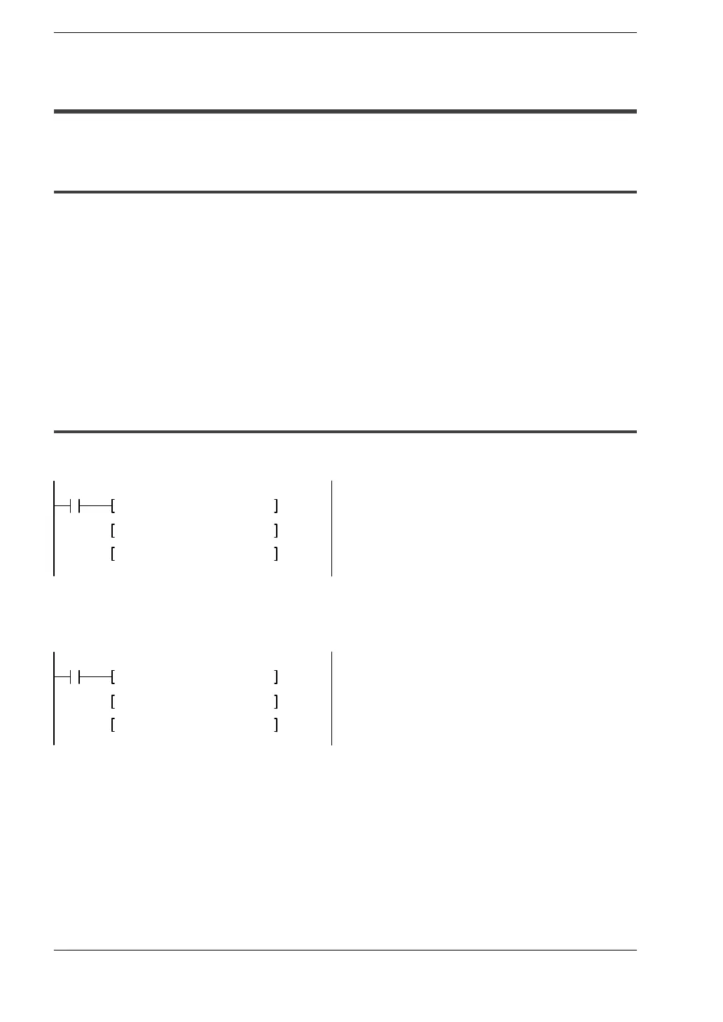
PWM output instruction (F170)
X6
F0 MV, H5, DT100
F0 MV, K500, DT101
F170 PWM, DT100, K0
While X6 is in the on state, a pulse with a period of 840 ms and duty ratio of 50% is output
from Y0.
X7
F0 MV, H6, DT100
F0 MV, K300, DT101
F170 PWM, DT100, K1
While X7 is in the on state, a pulse with a period of 1.6 s and duty ratio of 30% is output
from Y1.