14-62
14.3 Table of High-level Instructions
The high-level instructions are expressed by the prefixes “F” or “P” with numbers. For most of the high-
level instructions, “F” and “P” types are available. The differences between the two types are explained
as follows:
• Instructions with the prefix “F” are executed in every scan while its trigger is in the on.
• Instructions with the prefix “P” are executed only when the leading edge of its trigger is detected.
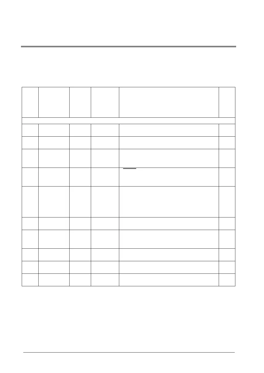
Num-
ber
Name Boolean Operand Description Steps
Data transfer instructions
F0
P0
16-bit data
move
MV
PMV
S, D (S)→(D) 5
F1
P1
32-bit data
move
DMV
PDMV
S, D (S+1, S)→(D+1, D) 7
F2
P2
16-bit data
invert and
move
MV
PMV/
S, D (S)→(D) 5
F3
P3
32-bit data
invert and
move
DMV/
PDMV/
S, D (S+1, S)→(D+1, D) 7
F4
P4
Reading of
head word
No. of the
specified
slot
GETS
PGETS
S, D The head word No. of the specified slot is read. 5
F5
P5
Bit data
move
BTM
PBTM
S, n, D The specified one bit in “S” is transferred to the
specified one bit in “D”. The bit is specified by “n”.
7
F6
P6
Hexadecimal
digit (4-bit)
data move
DGT
PDGT
S, n, d The specified one digit in “S” is transferred to the
specified one digit in “D”. The digit is specified by
“n”.
7
F7
P7
Two 16-bit
data move
MV2
PMV2
S1, S2, D (S1)→(D),
(S2)→(D+1)
7
F8
P8
Two 32-bit
data move
DMV2
PDMV2
S1, S2, D (S1+1, S1)→(D+1, D),
(S2+1, S2)→(D+3, D+2)
11
F10
P10
Block move BKMV
PBKMV
S1, S2, D The data between “S1” and “S2” is transferred to
the area starting at “D”.
7