S−LINK Control Unit FP0
4 − 12
4.6 S−LINK System Address Recognition
4.6.2 Address Setting of S−LINK I/O Device
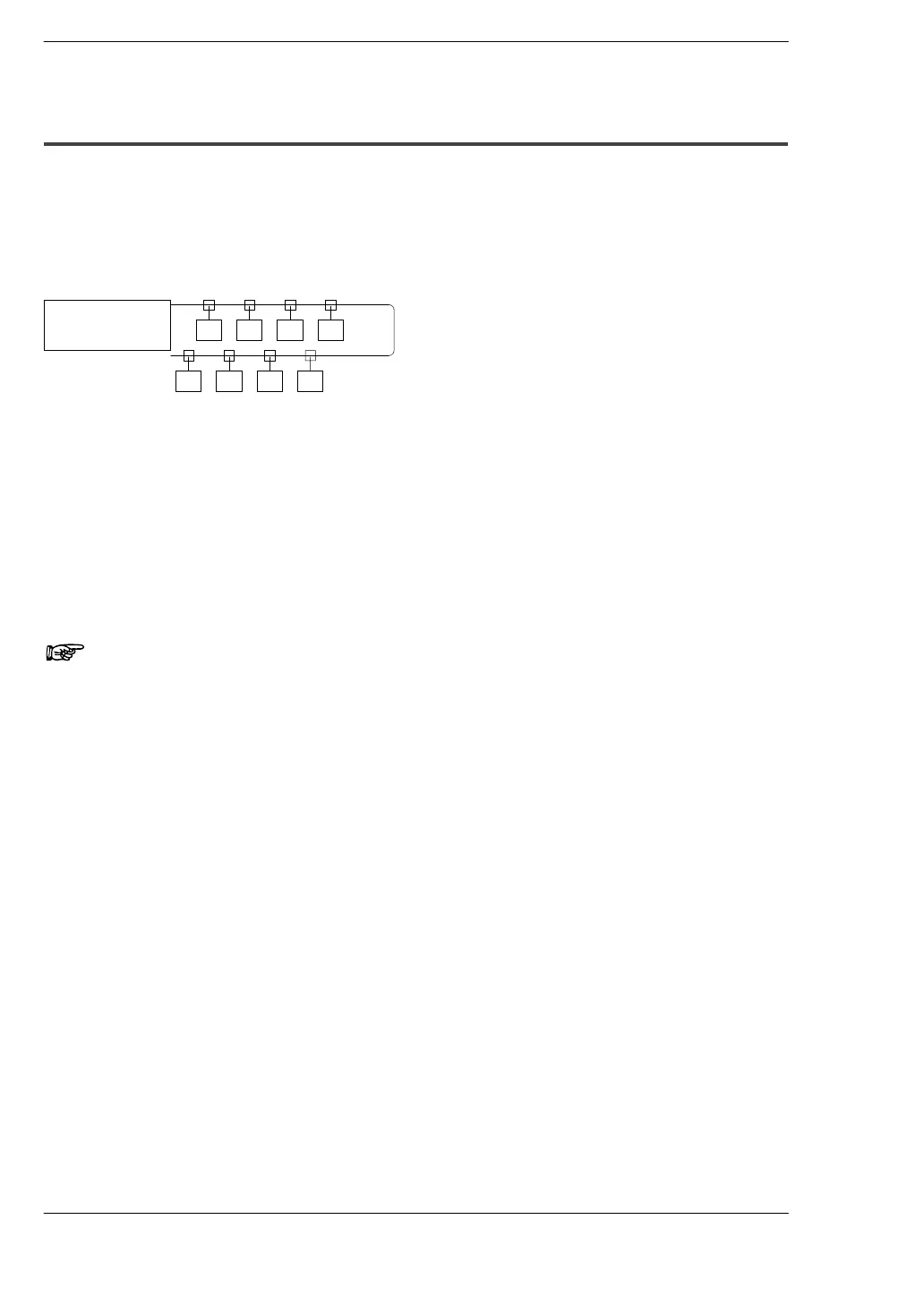
Addresses can be set freely, regardless of the position of the I/O device connected to
the system, but problems in the wiring of the main cable, such as broken or
disconnected wires, can be detected more easily if I/O devices closer to the S−LINK
control unit are given smaller addresses, and addresses increase in sequential order
for I/O devices which are farther away from the S−LINK control unit.
10 20 30 40
80 70 60 50
S−LINK
control unit
Numeric values indicate the initial address for each I/O
device.
Up to two I/O devices can be assigned the same address within the system for any
individual S−LINK control unit. Do not set the same address for three or more I/O
devices.
Up to seven boosters can be connected to one system for any individual S−LINK control
unit, but the actual number which can be connected varies depending on the units
configuring the system and the wiring length.
Note
The FP0 S−LINK control unit does not have a loop wiring
function.