I/O Allocation FP0
5 − 4
5.2 Control Unit
5.2 Control Unit
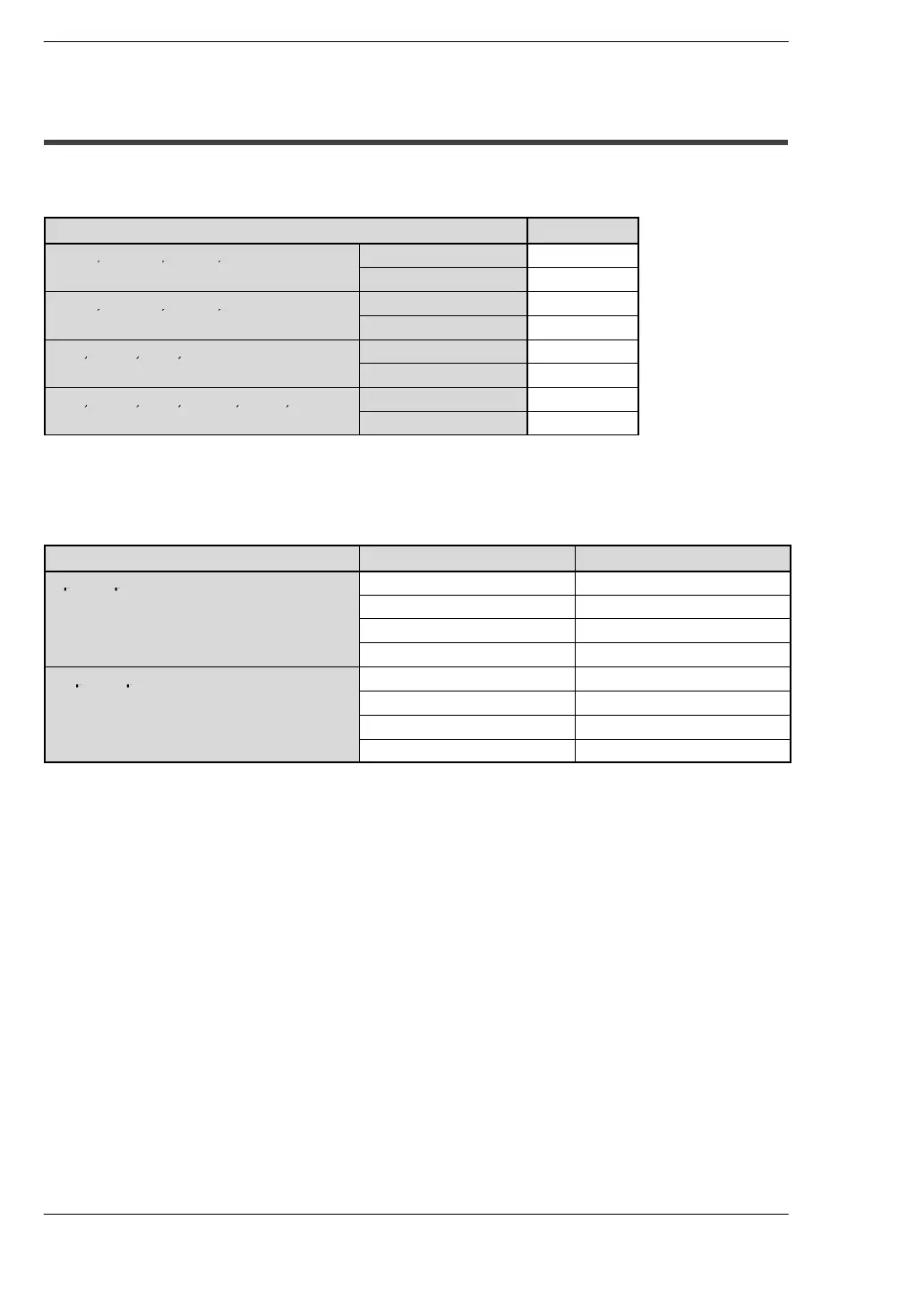
The I/O allocation of the FP0 control unit is fixed.
Type I/O number
C10RS, C10CRS, C10RM, C10CRM
Input: 6 points X0 to X5
Output: 4 points Y0 to Y3
C14RS, C14CRS, C14RM, C14CRM
Input: 8 points X0 to X7
Output: 6 points Y0 to Y5
C16T, C16CT, C16P, C16CP
Input: 8 points X0 to X7
Output: 8 points Y0 to Y7
C32T, C32CT, C32P, C32CP , T32CT, T32CP
Input: 16 points X0 to XF
Output: 16 points Y0 to YF
S−LINK Control Unit
The I/O allocation of the S−LINK control unit is fixed.
Unit FP0 I/O S−LINK address
Input: 64 points
X80 to X8F 0to15
X90 to X9F 16 to 31
X100 to X10F 32 to 47
X110 to X11F 48 to 63
Output: 64 points
Y80 to Y8F 64 to 79
Y90 to Y9F 80 to 95
Y100 to Y10F 96 to 111
Y110 to Y11F 112 to 127