Precautions During Programming FP0
8 − 8
8.3 Handling Index Registers
8.3.3 Example of Using an Index Register
Repeatedly Reading in External Data
Example:
Writing the contents of word external input relay WX3 to a
sequence of data registers beginning from DT0.
R0
F0 MV, K0, IX
R1
DF F0 MV, WX3, IXDT0
F35 +1, IX
1
2
3
1
When R0 turns on, K0 is written to index register IX.
2
When the R1 turns on, the contents of WX3 is transferred to
the data register specified by IXDT0.
3
Add 1 to IX.
In this case, the contents of IX will change successively,
and the destination data register will be as follows.
Input times
of R1
Contents of
IX
Destination
data register
1st
2nd
3rd
:
0
1
2
:
DT0
DT1
DT2
:
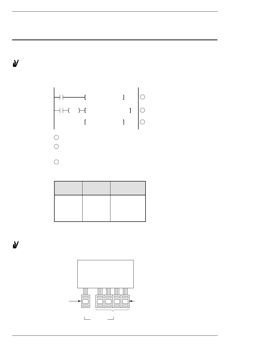
Inputting and Outputting Data Based on a Number Specified by an Input
Example 1: Setting a timer number specified by a digital switch
0 7 9 4
PLC
Timer set value
(timer time setting)
WX0
2
Digital
switches
WX1
Timer
setting
number