I/O AllocationFP0
5 − 5
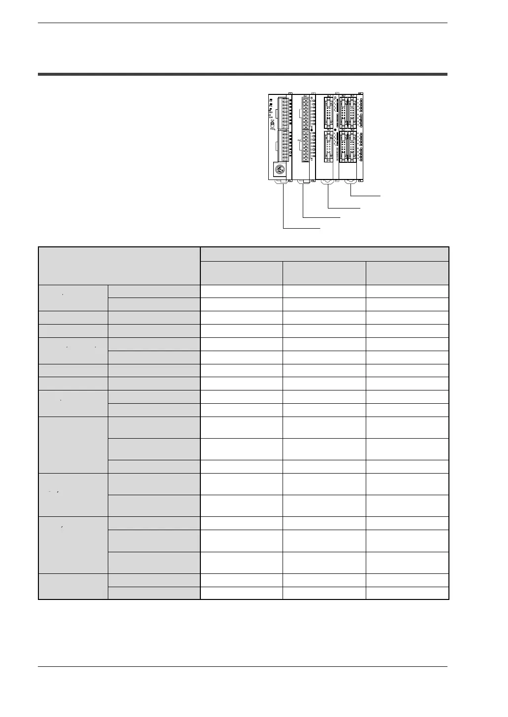
5.3 Expansion I/O Unit
5.3 Expansion I/O Unit
Up to three expansion I/O units can be added.
I/O numbers do not need to be set as I/O
allocation is performed automatically by
the FP0 control unit when an expansion
I/O unit is added.
The I/O allocation of expansion I/O unit
is determined by the installation location.
I/O number
Type
First expansion
Second
expansion
Third expansion
E8RS/E8RM
Input: 4 points X20 to X23 X40 to X43 X60 to X63
Output: 4 points Y20 to Y23 Y40 to Y43 Y60 to Y63
E8X Input: 8 points X20 to X27 X40 to X47 X60 to X67
E8YT/E8YP Output: 8 points Y20 to Y27 Y40 to Y47 Y60 to Y67
E16RS/E16RM/
Input: 8 points X20 to X27 X40 to X47 X60 to X67
E16T/E16P
Output: 8 points Y20 to Y27 Y40 to Y47 Y60 to Y67
E16X Input: 16 points X20 to X2F X40 to X4F X60 to X6F
E16YT/E16YP Output: 16 points Y20 to Y2F Y40 to Y4F Y60 to Y6F
E32T/E32P
Input: 16 points X20 to X2F X40 to X4F X60 to X6F
Output: 16 points Y20 to Y2F Y40 to Y4F Y60 to Y6F
A21
Input channel 0: 16
points
WX2
(X20 to X2F)
WX4
(X40 to X4F)
WX6
(X60 to X6F)
Input channel 1: 16
points
WX3
(X30 to X3F)
WX5
(X50 to X5F)
WX7
(X70 to X7F)
Output: 16 points WY2 (Y20 to Y2F) WY4 (Y40 to Y4F) WY6 (Y60 to Y6F)
A80,
TC4,
Input CH0, 2, 4, 6: 16
points
WX2
(X20 to X2F)
WX4
(X40 to X4F)
WX6
(X60 to X6F)
TC8
Input CH1, 3, 5, 7: 16
points
WX3
(X30 to X3F)
WX5
(X50 to X5F)
WX7
(X70 to X7F)
A04V, A04I
Input: 16 points WX2 (X20 to X2F) WX4 (X40 to X4F) WX6 (X60 to X6F)
Output CH0, 2, 4, 6: 16
points
WY2
(Y20 to Y2F)
WY4
(Y40 to Y4F)
WY6
(Y60 to Y6F)
Output CH1, 3, 5, 7: 16
points
WY3
(Y30 to Y3F)
WY5
(Y50 to Y5F)
WY7
(Y70 to Y7F)
IOL
Input: 32 points X20 to X3F X40 to X5F X60 to X7F
Output: 32 points Y20 to Y3F Y40 to Y5F Y60 to Y7F
− The channel data of FP0−A80, TC4, TC8, A04V and A04I will switch and be read or
written by a user program that contains the conversion data switch flag.
− Please verify with the manual for the FP0 CC−Link Slave unit.
Third expansion
Second expansion
First expansion
Control unit