High−speed Counter/Pulse Output/ PWM Output FP0
9 − 20
9.4 Pulse Output Function
9.4.3 I/O Allocation and Wiring
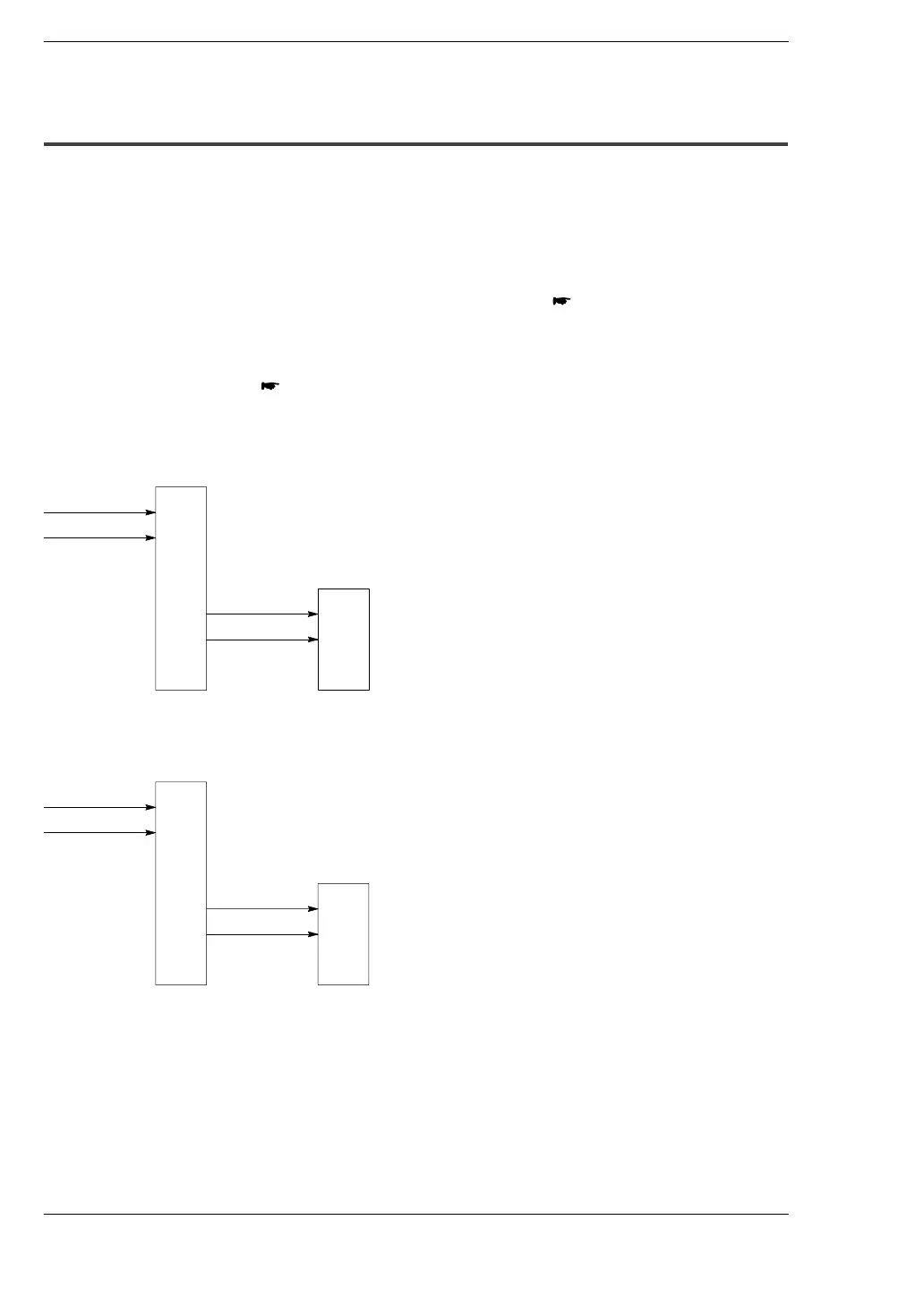
Single pulse input driver (pulse input and directional switching input)
One output point is used as a pulse output and the other output is used as a directional
output.
The pulse output terminal, directional output terminal, and home input I/O allocation is
determined by the channel used. For detailed information
section 9.2.1
Near home input is substituted by allocating the desired contact point and turning on
and off the specified bit of DT9052/DT90052.
For detailed information
F0 (MV)
Up to two driver systems can be connected.
When using CH0
X0
X2
Y0
Home input
Near home
input
Pulse output
*
Y2
Directional
switching output
FP0
Driver
* The near home input specifies the desired input, such as X2.
When using CH1
Home input
Near home
input
Pulse output
Directional
switching output
Driver
X1
X3
Y1
*
Y3
FP0
* The near home input specifies the desired input, such as X3.