S−LINK Control UnitFP0
4 − 3
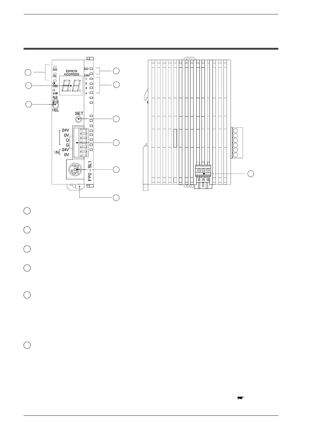
4.1 Names and Functions
4.1 Names and Functions
7
4
6
10
5
3
8
9
1
2
1
Status indicator LED
The LED display the operation mode and error statuses.
2
ERROR ADDRESS display (2−digit hexadecimal display)
The address at which the S−LINK system error occurred is displayed.
3
Mode switch
The mode switch changes the operation mode.
4
Transmission indicator (SEND)
This flashes when input or output data is transmitted between the various units of
the S−LINK system.
5
ERROR indicators
These light if an error occurs in the S−LINK system.
ERR1 (Error 1): Short circuit between D − G line.
ERR2: Unused
ERR3 (Error 3): Abnormal voltage level between D − G line.
ERR4 (Error 4): Broken wire or S−LINK I/O device error
6
System SET button
Pressing the system SET button reads the connection status for the S−LINK
system and stores it in the memory. In subsequent operation, the S−LINK unit
checks for errors using the connection status registered at this time.
The output unit data effective at the time that the system SET button was pressed
is retained.
next page