14-28
14.2 Table of Basic Instructions
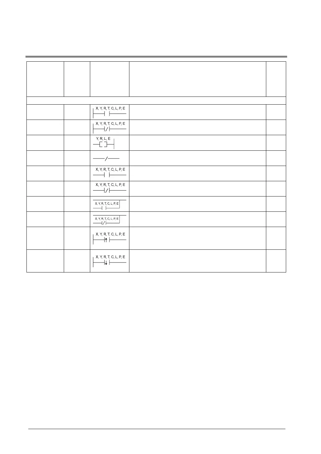
Name Boolean Symbol Description
Steps
Note1)
Sequence basic instructions
Start
ST Begins a logic operation with a Form A (normally open)
contact.
1 (2)
Start Not
ST/ Begins a logic operation with a Form B (normally closed)
contact.
1 (2)
Out
OT
Outputs the operated result to the specified output.
1 (2)
Not
/
Inverts the operated result up to this instruction.
1
AND
AN Connects a Form A (normally open) contact serially.
1 (2)
AND Not
AN/ Connects a Form B (normally closed) contact serially.
1 (2)
OR
OR Connects a Form A (normally open) contact in parallel.
1 (2)
OR Not
OR/ Connects a Form B (normally closed) contact in parallel.
1 (2)
Leading
edge start
ST↑ Begins a logic operation only for one scan when the
leading edge of the trigger is detected.
2
Trailing edge
start
ST↓ Begins a logic operation only for one scan when the trailing
edge of the trigger is detected.
2
Note1) In the FP2/FP2SH/FP10SH, when using X1280, Y1280, R1120 (special internal relay included),
L1280, T256, C256 or anything beyond for the ST, ST/, OT, AN, AN/, OR and OR/ instructions,
the number of steps is shown in parentheses. Also, in the FP2/FP2SH/FP10SH, when a relay
number has an index modifier, the number of steps is shown in parentheses.