S−LINK Control Unit FP0
4 − 6
4.2 Specifications
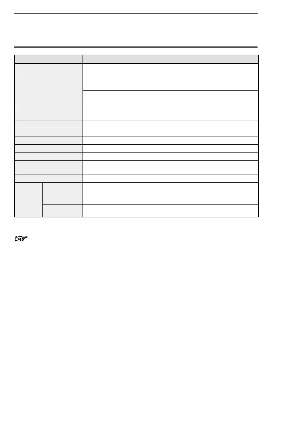
4.2.2 S−LINK Controller Specifications
Item Description
−
−
−
a
e
power supp
yvo
age
+
−
owa
er
pp
ep− p+
−
max.
upp
e
rom
− 24
,
− 0
o
t
e
−
term
na
oc
Current consumption [S−LINK controller current consumption (including D − G line current consumption)]
(* note 1)
24V DC 1.6A max.
−
ax
mum curren
w
c
can
e supp
e
supp
e
o
−
un
an
ev
ces
rom 24
− 0
ne
+24
5
use: 5
Transmission method Bi−directional time−divided multiple signal transmission
Synchronization method Bit synchronization, frame synchronization
Transmission protocol S−LINK protocol
Transmission speed 28.5kbps
Transmission delay time Max. 10.7ms
ransm
ss
on
stance
a
ns
gna
w
re: up to a
stance to 200m max.
400m w
en a
ooster
s use
FAN−out (* note 2) 320
Connection method
(* note 3)
‘T’−branch multi−drop wiring
No. of input/output points 64 points input/64 points output Fixed
Display
indicators
Transmission
display (SEND)
Green LED blinks in response to synchronization signals
Error indicator Red LED light up depending on the error
Error address
display
If the system error occurs, the error address is displayed using the red 7−segment
LED.
Notes
1) For detailed information on current consumption, refer to
“Determining the Power Supply” in the “S−LINK Design
Manual.”
2) The output capacitance for the D−G line of the S−LINK
controller and booster is indicated by FAN−out, and the input
capacitance from the D−G line of the S−LINK configuration
unit is indicated by FAN−in. When configuring the S−LINK
system, the configuration should be set up so that the
FAN−out total > or = the FAN−in total. (For detailed information
on calculating the FAN−in value and other values, see the
“S−LINK Design Manual.”
3) The FP0 S−LINK control unit does not have a loop wiring
function.