S−LINK Control Unit FP0
4 − 4
4.1 Names and Functions
7
S−LINK terminal block (6−pin)
The power supply and signal wires of the S−LINK system are connected to the
S−LINK terminal block.
The S−LINK terminal block can be detached from the FP0 S−LINK control unit for
wiring operations.
For detailed information, refer to section “4.3.2 Wiring to S−LINK Terminal Block.”
8
Tool port (RS232C)
The tool port (RS232C) is used to connect a programming tool.
9
Power supply connector
Supply 24V DC to the power supply connector. It is connected using the power
supply cable (AFP0581) that comes with the unit.
10
RS232C port
Use this port to connect to devices with an RS232C port, such as an I.O.P., a bar
code reader, or an image checker, enabling data input and output.
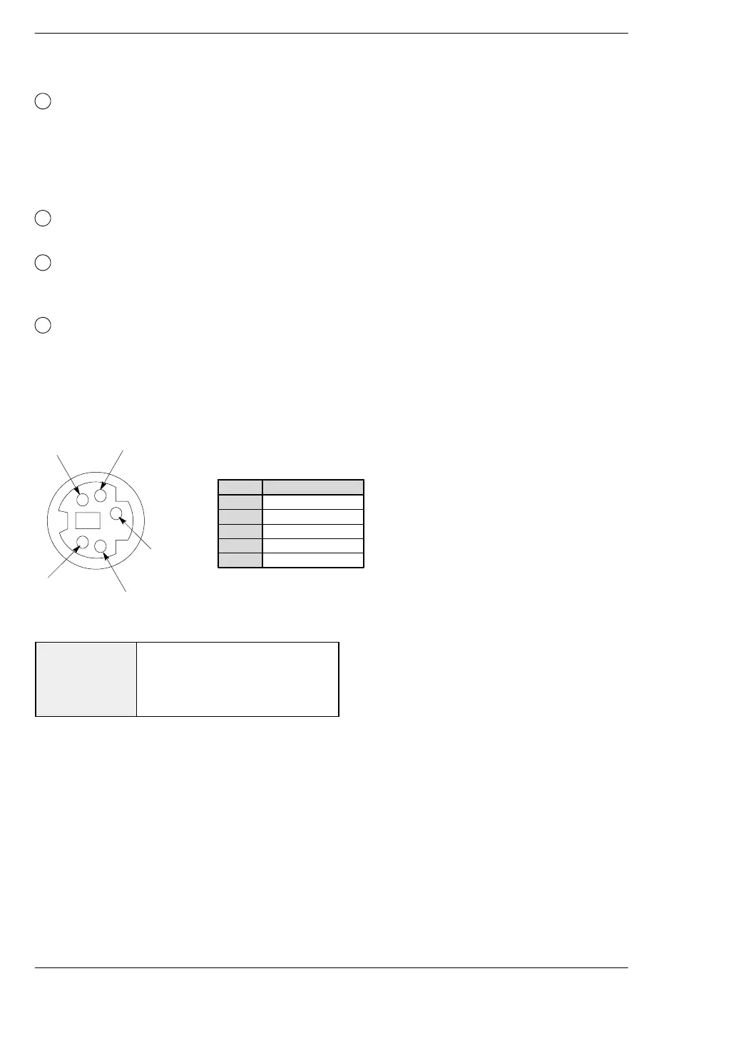
Tool port (RS232C) specifications
Pin assignment
3
4
5
1
2
Abbreviation
SG
SD (TXD)
RD (RXD)
+5V
—
Pin no.
3
2
4
1
5
Settings when shipped from the factory
Default value Baud rate: 9600bps
Character bit: 8bits
Parity check: Odd
Stop bit: 1bit