Precautions During ProgrammingFP0
8 − 9
8.3 Handling Index Registers
R0
DF F81 BIN, WX1, IX
1
2
F81 BIN, WX0, IXSV0
1
Convert the BCD timer number data in WX1 to binary and
set it in index register IX.
2
Convert the BCD timer set value in WX0 to binary and
stored in the timer set value area SV specified by contents
of IX.
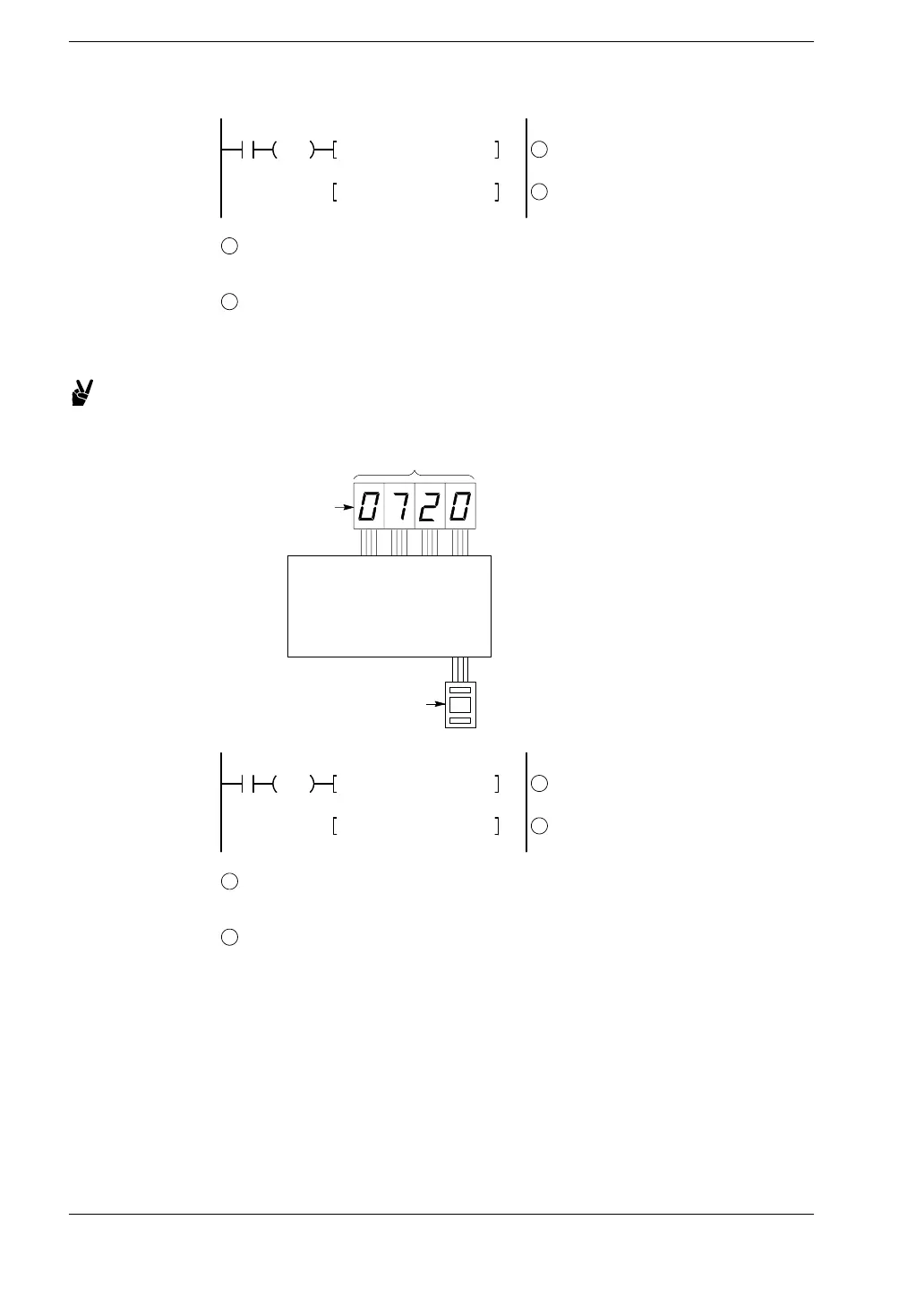
Example 2: External output of the elapsed value in a timer number specified
by a digital switch
1
PLC
WX1
7-segmenet
indicator
WY0
R1
DF F81 BIN, WX1, IX
1
2
F80 BCD, IXEV0, WY0
Timer elapsed
value display
Digital
switches
Timer
number
setting
1
Convert the BCD timer number data in WX1 to binary, and
set it in index register IX.
2
Convert the elapsed value data EV in the timer specified by
IX to BCD, and output it to word external output relay WY0.