S−LINK Control Unit FP0
4 − 8
4.3 Wiring the Power Supply
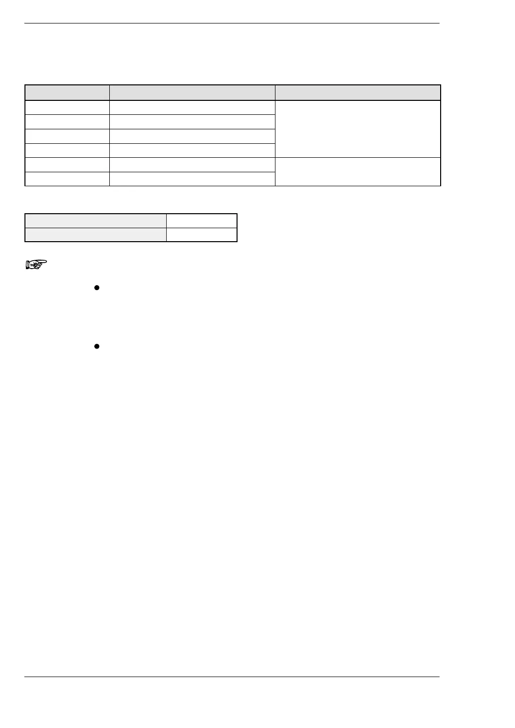
S−LINK terminal block: MC1.5/6−ST−3.5 (Made by Phoenix Contact Co.)
Terminal name Color of connecting cable Description
24V Brown Main wire (for S−LINK I/O devices)
0V Blue
D White
G Black
IN−24V — External power supply input for S−LINK
IN−0V —
Suitable wires (twisted wire)
Size AWG#20 to 16
Normal cross−section surface area 0.5 to 1.25mm
2
Notes
The S−LINK section is protected by a fuse, but if too many
input/output devices are connected, or if the current
consumption is heavy enough to cause the fuse to blow, we
recommend providing a local power supply.
A short−circuit between D−G, or between D−24V, triggers the
protective circuit, but there is no protection against
short−circuiting between G−24V or 0V−24V. Be aware that a
short−circuit can cause a breakdown or malfunction.