Expansion I/O UnitsFP0
3 − 21
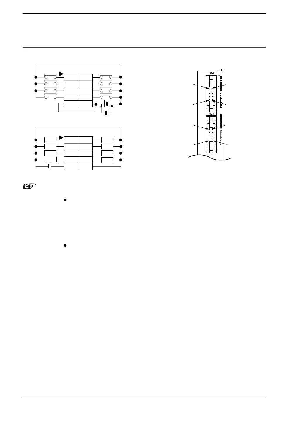
3.4 Pin Layouts
3.4.4 E16P
COM
X25
X27
X21
X23
COM
X24
X26
X20
X22
(−)
Y25
Y27
Y21
Y23
(+)
Y24
Y26
Y20
Y22
Input
Output
Load
Load
Load
Load
Load Load
Load
X21
Y21
(−)
X20
Y20
(+)
COM
COM
E16P
Load
(* Note 1)
Notes
The two COM terminals of input terminals are connected
internally, however they should be externally connected as
well.
1) Either positive or negative polarity is possible for the input
voltage supply.
The I/O number given above is the I/O number when the
expansion I/O unit is installed as the first expansion unit.
The I/O numbers for the expansion I/O units will differ
depending on the location where they are installed
(*section 5.3).