Service Manual 7 Measuring System
7.1 General
1/09 PERFECTA 115 / 132 / 168 / 225 – TS 42
PERFECTA Schneidemaschinenwerk GmbH D-02625 Bautzen Schäfferstr. 44 Tel.: +49-3591-556-131 to -133 Fax: +49 3591-556-139
7. Measuring System
7.1 General
On PERFECTA machines, the actual and desired measurements are displayed by
the user interface.
In this connection, you can choose among four different units. Please refer to the
"Settings" menu in the Operating Manual.
The machines are factory-set to metric units.
During operation, i. e. while the backgauge is running, the measurements are auto-
matically monitored. After 70 travels since the last monitoring, and before each back-
gauge event is started, the control system checks whether a zero pulse is expected
within the range of 0.5 mm before the target position.
If so, the brake ramp will be started earlier to enable the expected zero pulse to be
evaluated. If the zero pulse appears at the expected position the counter will be reset
and begin to count up again.
If there is no zero pulse at the expected position a "Please calibrate" message will be
raised.
If already 100 travels have been done without the opportunity of measurement checking
deceleration will be initiated already 5 mm before the target position at the next travel
which will be longer than 5 mm. Thus, the last 4 mm will be done at slow speed.
Within these 4 mm, there will, at any rate, be a zero pulse (4 mm = one motor revolution,
i. e. one zero pulse per revolution) which can be used for evaluation.
If the zero pulse appears at the expected position the counter will be reset and begin
to count up again.
If there is no zero pulse at the expected position a "Please calibrate" message will be
displayed.
7.2 Adjusting the proximity switches
Adjust front proximity switch B39 so as to get activated at 200 ± 50 pulses (= 2 ± 0.5 mm)
below the measurement of 200 mm (= the display reads 20,000 pulses) when the
backgauge is running forward, i. e. at a count of, for example, 19974 for the first zero
pulse below the 20,000 mark, proximity switch B39 must become active within the
range of 20174 ± 50. Please refer to the "Sensor Test" menu.
Adjust rear proximity switch B27 so as to get activated at the rear table length + 2 mm
position.
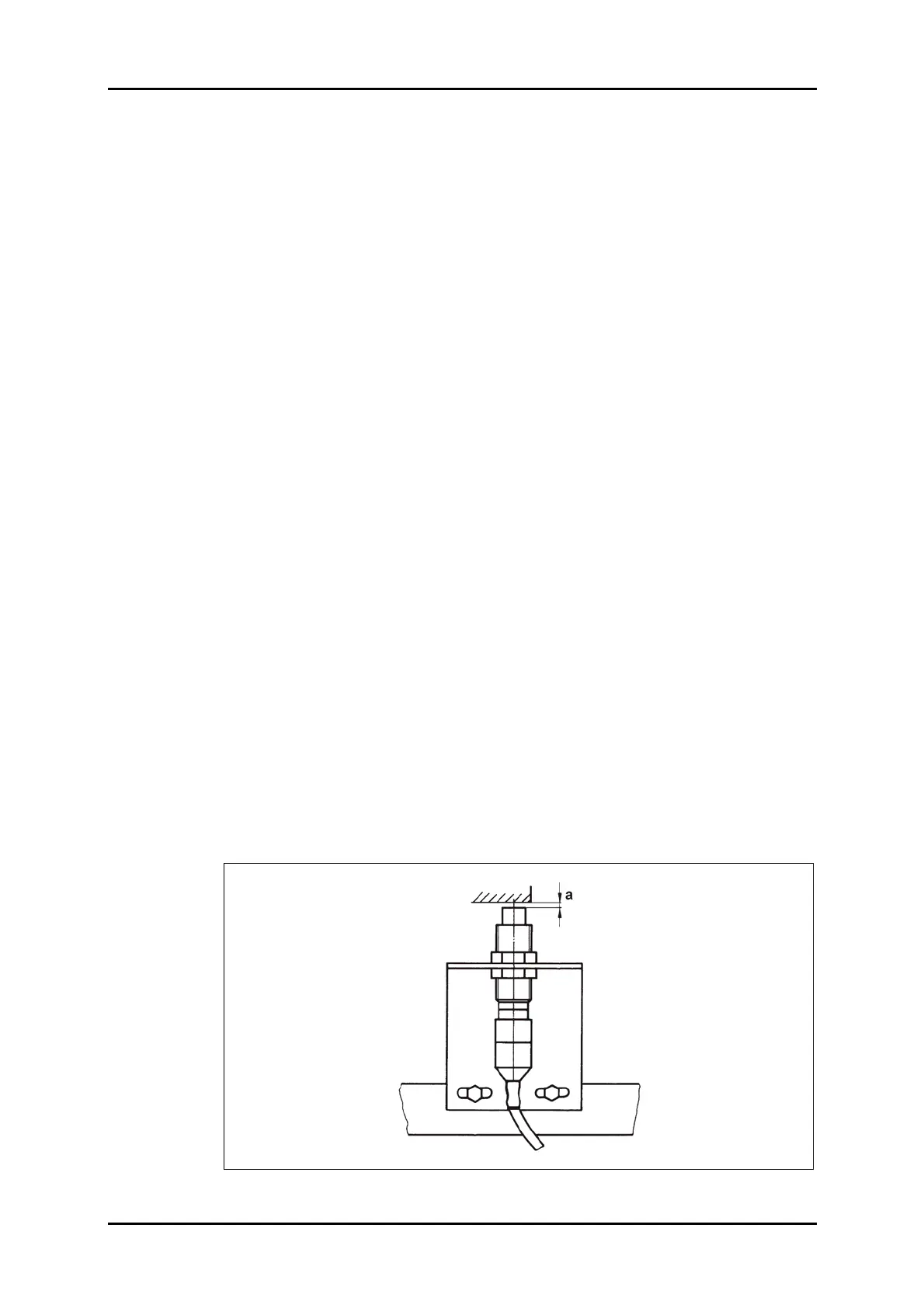
In this connection, adjust both proximity switches so that distance a between the
switch and the vane is 1.5 + 0.5 mm (refer to Figure 31).
Figure 31: Proximity switch.