Service Manual 8 Hydraulic Clamping System
8.2 Hydraulic clamping system working phases
1/09 PERFECTA 115 / 132 / 168 / 225 – TS 46
PERFECTA Schneidemaschinenwerk GmbH D-02625 Bautzen Schäfferstr. 44 Tel.: +49-3591-556-131 to -133 Fax: +49 3591-556-139
8.2 Hydraulic clamping system working phases
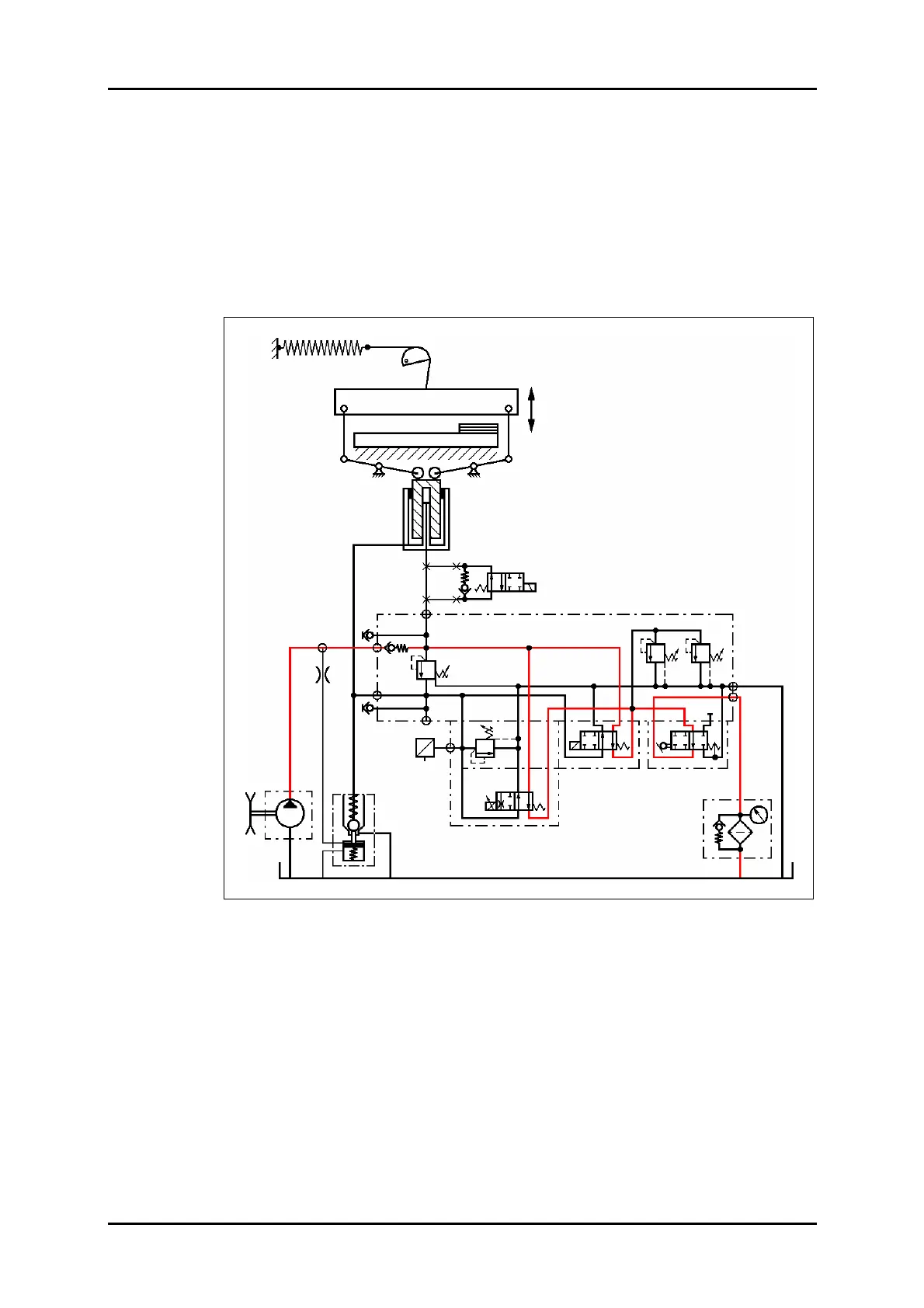
8.2.1 Machine in normal position (free circulation)
The main motor is running. The pump is running. The knife beam and the clamp are
at their topmost positions.
Multiway valves VW1 and VW2 are at their normal resting positions (Y90 and Y60 are
not energized).
The oil flows in an almost pressureless condition back into the tank via RV1, VW1,
VW2, VDR and F.
Figure 34: Normal position hydraulic circuit diagram.
VD1.1 VD1
STV
VD2
VDR
VW1
VW2
VD3
SRV
P
F
Z
Option: Stop valve
PE
M1
M2
PZ
P
(PV)
T1
T2
RV1
DR1
D-Sensor
U
I
B90
Y90
Y60
Y62