Service Manual 9 Clamping pressure basic adjustments
9.1 Amplifier card setting instructions
1/09 PERFECTA 115 / 132 / 168 / 225 – TS 59
PERFECTA Schneidemaschinenwerk GmbH D-02625 Bautzen Schäfferstr. 44 Tel.: +49-3591-556-131 to -133 Fax: +49 3591-556-139
9. Clamping pressure basic adjustments
9.1 Amplifier card setting instructions
1. Set the safety valve to maximum pressure
2. Bring pot P7 to middle position; note that it is a 20 turn setting device.
3. Feed in the maximum command signal.
(A setting of 100 % on the display corresponds to approx. 8.5 V at terminals 4/5 of
the amplifier card input.)
Start the machine for cutting; if the clamp does not move readjust pots P4 and P6
about three turns in clockwise direction.
Use P2 to set a voltage of 6.2 V between measuring points MP1 and MP2.
4. Bring the command signal to maximum (5 % corresponds to some 0.5 V).
Use trimming pot P4 to set the maximum actual value.
The critical value is at a solenoid current of some 1.0 A or at a minimum pressure
of 7 bar.
The current depends on the solenoid temperature.
5. Bring the output voltage from the computer to 100 % and use P6 to set the machine-
specific maximum pressure plus approx. 3 bar.
6. Set the maximum pressure on the display and adjust the safety valve on the machine-
specific pressure as shown in the table below.
Use a load cell to check the minimum and maximum clamp pressing force values.
Machine size 115 132 168 225
min. 0.2 0.2 0.3 0.35
Clamping pressure (MPa)
max. 12 12 16 20
min. 3 3 3.5 4
Clamping force (kN)
max. 45 45 60 100
Table 3: Clamping pressure and clamping force values.
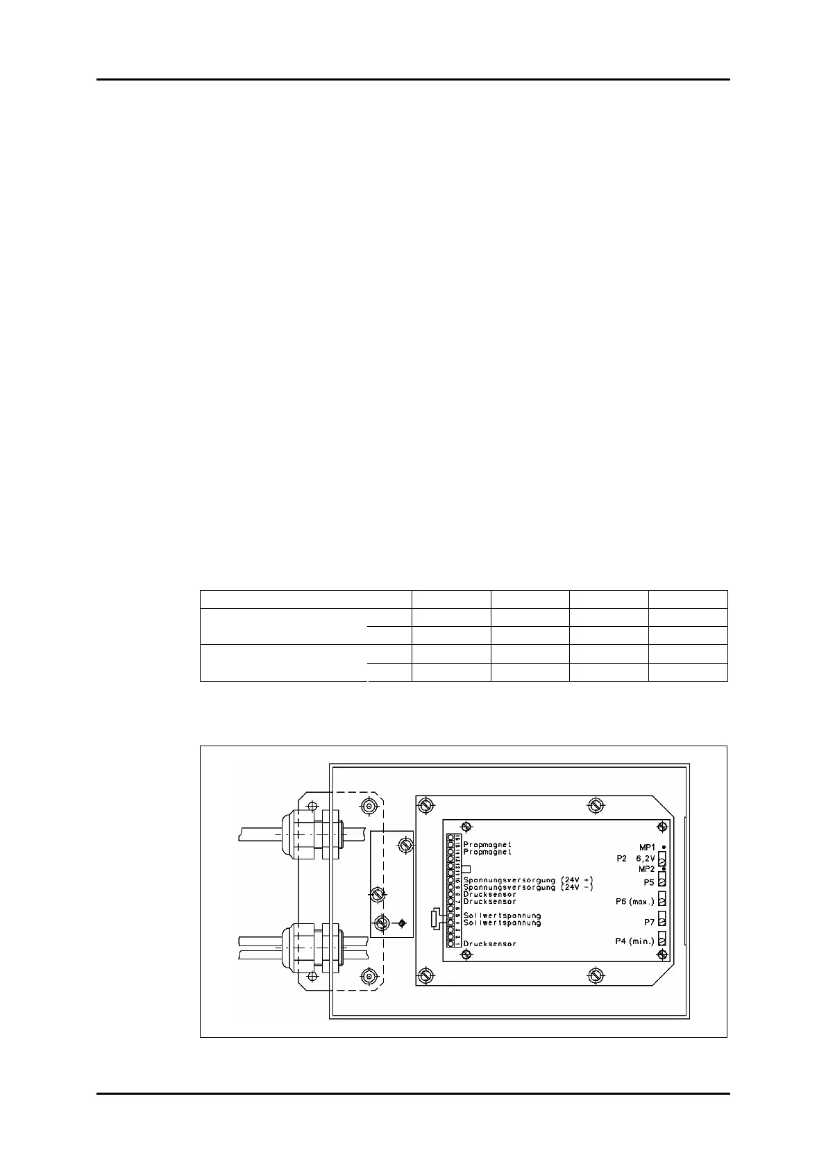
Figure 40: Amplifier card installation position.