Service Manual 7 Measuring System
7.3 Calibrating the measuring system
1/09 PERFECTA 115 / 132 / 168 / 225 – TS 43
PERFECTA Schneidemaschinenwerk GmbH D-02625 Bautzen Schäfferstr. 44 Tel.: +49-3591-556-131 to -133 Fax: +49 3591-556-139
7.3 Calibrating the measuring system
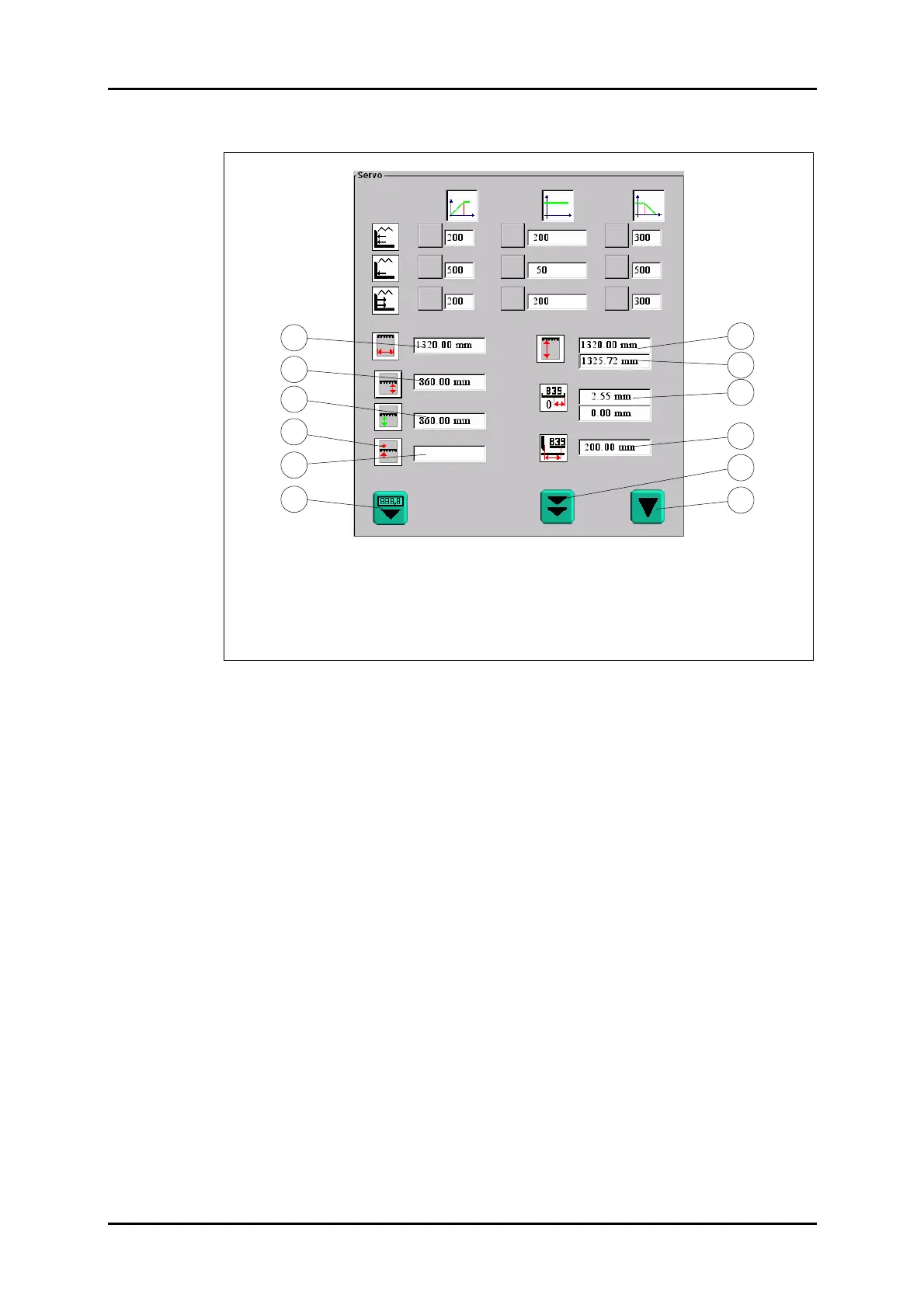
1. Cutting width
2. Current desired measurement
3. Current actual measurement
4. "Correct" key
5. Correction actual measurement
6. "Set Measurement" key
7. Rear table length acc. to machine model
8. Measured rear table length
9. Current first zero point
10. B39 position
11. Factory calibration
12. Operator's calibration
Figure 32: "Servo" menu.
1. Power up the machine.
2. Calibrate the machine (operator's calibration, or factory calibration, if required).
3. Set the backgauge mechanically to 200.00 (use a steel ruler), then have the
switching point of B39 indicated. When doing so, note the switching hysteresis.
4. Take the actual distance between the knife back and the backgauge (use a steel
ruler or a sliding calliper to measure on the material to be cut).
5. Type the measurement into field 5 of the "Servo" menu.
• Field 5 must be highlighted blue before. To do so, press key 4.
• To take over as the current actual measurement of the machine the measure-
ment you have determined press the left-hand cut-release pushbutton, keep it
pressed and, at the same time press key 6.
6. Move the backgauge to 200.00 mm.
7. Check:
• Enable manual backgauge control.
• Call the "Diagnostic" menu.
• Manually move back the backgauge until the LED of B39 goes out, then slowly
bring the backgauge forward until the LED of B39 lights green.
• Call the main menu, determine the position and, if it is not within the range of
200.00 ± 0.50, shift B39 correspondingly.
8. Calibrate the machine (factory calibration).
9. Check the measurement again as per item 7.
10. Check the tolerances.
Field 9 (first line) must read a value between 1.5 und 3.5 mm.
• If the range is not kept in field 9 relocate the toothed belt (90° steps) with respect
to the armature disk.
11. Calibrate the machine (factory calibration).
12. Check the tolerance again as per item 10.
13. Check the measurement.
7
10
9
2
4
1
5
6
11
12
8
3