Service Manual 8 Hydraulic Clamping System
8.2 Hydraulic clamping system working phases
1/09 PERFECTA 115 / 132 / 168 / 225 – TS 48
PERFECTA Schneidemaschinenwerk GmbH D-02625 Bautzen Schäfferstr. 44 Tel.: +49-3591-556-131 to -133 Fax: +49 3591-556-139
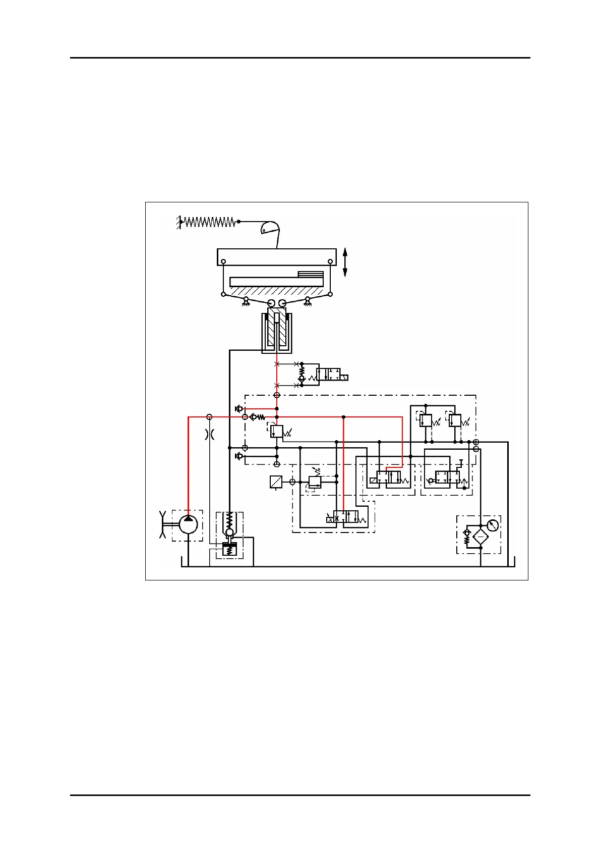
8.2.3 Cut triggering
When the cut-release pushbuttons are pressed the computer will actuate Y90/VW1
and Y60/VW2.
In this connection, the voltage determined by the computer will be applied to Y90.
This will block the oil circulation, and the oil flow set on VD2 will be applied to the fast-
speed piston of cylinder Z. The plunger will extend at fast speed and move down the
clamp. The large cylinder chamber will fill with oil via SRV.
When the clamp comes to rest on the table SRV will turn off, and the pressure preset
on Y90 through the computer will be obtained in the main pressure chamber.
Figure 36: Cut triggering hydraulic circuit diagram.
VD1.1 VD1
STV
VD2
VDR
VW1
VW2
VD3
SRV
P
F
Z
Option: Stop valve
PE
M1
M2
PZ
P
(PV)
T1
T2
RV1
DR1
D-Sensor
U
I
B90
Y90
Y60
Y62