Service Manual 8 Hydraulic Clamping System
8.2 Hydraulic clamping system working phases
1/09 PERFECTA 115 / 132 / 168 / 225 – TS 51
PERFECTA Schneidemaschinenwerk GmbH D-02625 Bautzen Schäfferstr. 44 Tel.: +49-3591-556-131 to -133 Fax: +49 3591-556-139
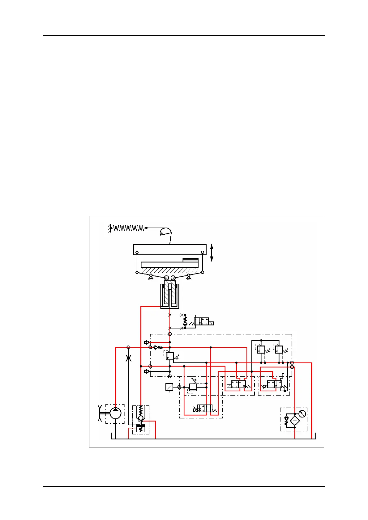
8.2.6 Clamp return
As a result of the decompression, VD3 will no longer be flown through, the pressure
switch will not detect any volume flow, thus turning on Y2/VW2, whereby the flow
cross section for the oil to be displaced from the cylinder chambers will be increased.
The clamp will be moving up.
The pressure fall in the pump line will open suction valve SRV, and the oil flow from
the main pressure chamber will pass through this valve to return into the tank.
The clamp will be returned to its topmost position by tension springs, whereby the oil
is forced from the cylinder chambers into the tank.
When the end position in the clamping cylinder is reached the last stroke section will
be dampened without any jerking. The machine will return to its normal position as
shown in Figure 34.
Clamp stroke limitation
The clamp stroke limitation option can be selected from the "Settings" menu of the
machine (refer to the Operating Manual).
After a short stroke (the clamp has lifted off the pile), the oil to be displaced will be
trapped in the fast-speed piston chamber and the clamp held at this position.
Figure 39: Clamp return hydraulic circuit diagram.
VD1.1 VD1
STV
VD2
VDR
VW1
VW2
VD3
SRV
P
F
Z
Option: Stop valve
PE
M1
M2
PZ
P
(PV)
T1
T2
RV1
DR1
D-Sensor
U
I
B90
Y90
Y60
Y62