Service Manual 8 Hydraulic Clamping System
8.2 Hydraulic clamping system working phases
1/09 PERFECTA 115 / 132 / 168 / 225 – TS 47
PERFECTA Schneidemaschinenwerk GmbH D-02625 Bautzen Schäfferstr. 44 Tel.: +49-3591-556-131 to -133 Fax: +49 3591-556-139
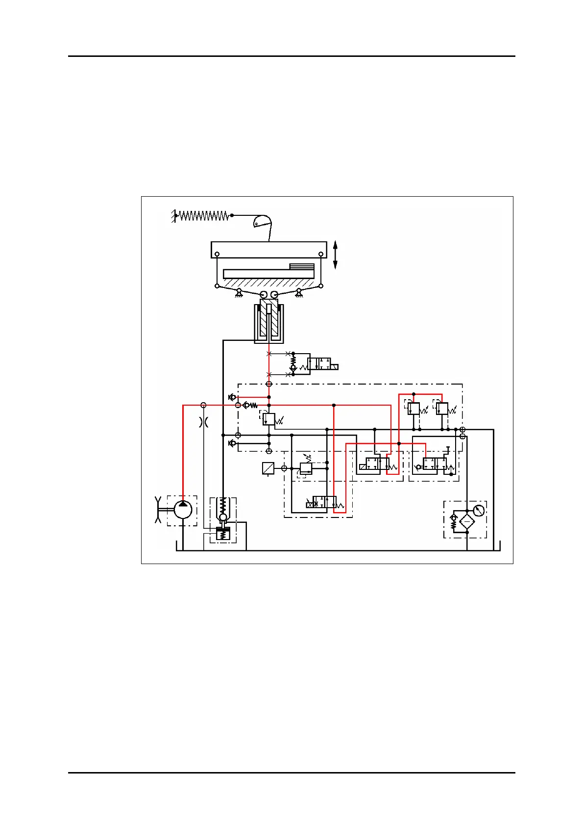
8.2.2 Preclamping
VDR is actuated from the normal position via the pedal.
The previous flow through VW1/VW2 is closed. Pressure is building up from pump P
via RV1, VW1/VW2 and VD1, VD1.1 which determine the pressure value. The oil flow
is directed to the fast speed piston.
The plunger of cylinder Z extends and moves down the clamp. The large cylinder
chamber fills with oil via SRV.
Once the clamp comes to rest on the table, the oil will flow back into the tank via VD1
and VD1.1.
Figure 35: Preclamping hydraulic circuit diagram.
VD1.1 VD1
STV
VD2
VDR
VW1
VW2
VD3
SRV
P
F
Z
Option: Stop valve
PE
M1
M2
PZ
P
(PV)
T1
T2
RV1
DR1
D-Sensor
U
I
B90
Y90
Y60
Y62