Service Manual 8 Hydraulic Clamping System
8.2 Hydraulic clamping system working phases
1/09 PERFECTA 115 / 132 / 168 / 225 – TS 49
PERFECTA Schneidemaschinenwerk GmbH D-02625 Bautzen Schäfferstr. 44 Tel.: +49-3591-556-131 to -133 Fax: +49 3591-556-139
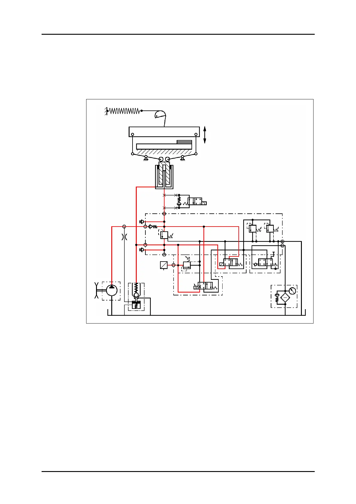
8.2.4 Main clamping action
The oil flow coming from the pump is completely directed into the main pressure
chamber via VD2.
The voltage coming from the control module via the amplifier card of VW1 will be
transformed into a power signal and reflects the pressure in the main chamber which
is proportional to the set value in the touch screen.
Figure 37: Main clamping action hydraulic circuit diagram.
VD1.1 VD1
STV
VD2
VDR
VW1
VW2
VD3
SRV
P
F
Z
Option: Stop valve
PE
M1
M2
PZ
P
(PV)
T1
T2
RV1
DR1
D-Sensor
U
I
B90
Y90
Y60
Y62