Pulse Width Modulator (PWM) 232 May 03, 2004
Philips Semiconductors Preliminary User Manual
LPC2119/2129/2194/2292/2294ARM-based Microcontroller
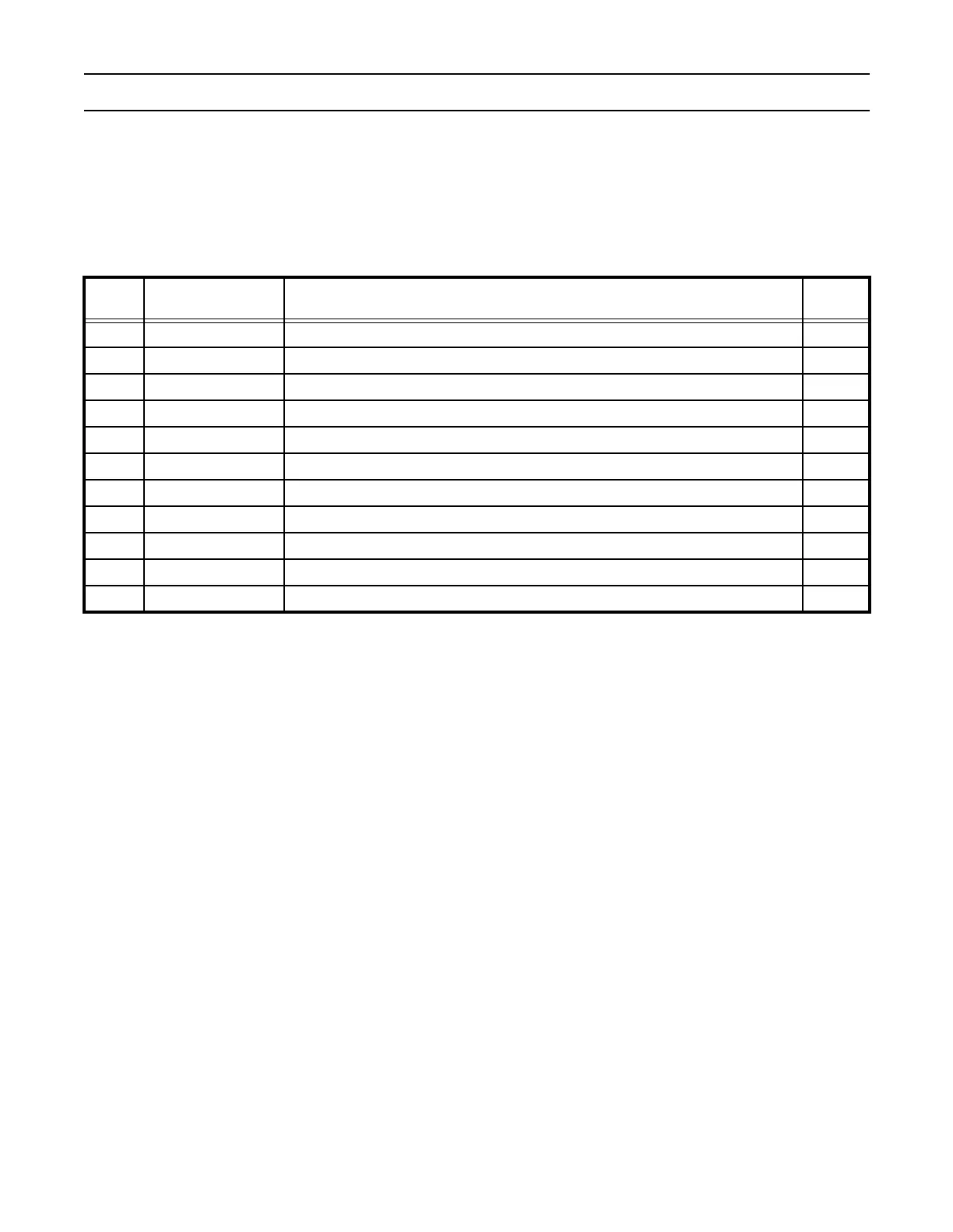
PWM Interrupt Register (PWMIR - 0xE0014000)
The PWM Interrupt Register consists of eleven bits (Table 167), seven for the match interrupts and four reserved for the future
use. If an interrupt is generated then the corresponding bit in the PWMIR will be high. Otherwise, the bit will be low. Writing a
logic one to the corresponding IR bit will reset the interrupt. Writing a zero has no effect.
Table 167: PWM Interrupt Register (PWMIR - 0xE0014000)
PWMIR Function Description
Reset
Value
0 PWMMR0 Interrupt Interrupt flag for PWM match channel 0. 0
1 PWMMR1 Interrupt Interrupt flag for PWM match channel 1. 0
2 PWMMR2 Interrupt Interrupt flag for PWM match channel 2. 0
3 MR3 Interrupt Interrupt flag for PWM match channel 3. 0
4 Reserved. Application must not write 1 to this bit. 0
5 Reserved. Application must not write 1 to this bit. 0
6 Reserved. Application must not write 1 to this bit. 0
7 Reserved. Application must not write 1 to this bit. 0
8 PWMMR4 Interrupt Interrupt flag for PWM match channel 4. 0
9 PWMMR5 Interrupt Interrupt flag for PWM match channel 5. 0
10 PWMMR6 Interrupt Interrupt flag for PWM match channel 6. 0