TERMINALS CONDITIONS STANDARD
5 - 23 Switch in position "ON"
Switch on "RUN"
Side stand raised
Electric fan off
Battery voltage
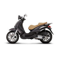
CIRCUIT LAYOUT
Specification
Desc./Quantity
1 Electronic control unit
2 Electric fan
3 Fuse 30A
4 Key switch
5 Electric fan remote control switch
The electric fan system is powered by a remote
control switch connected to the continuous power
supply controlled by the electronic control unit of
the injection system.
The electronic control unit of the injection system
controls the electric fan in relation to the measured
engine temperature.
If prolonged running of the electric fan is noticed,
check the following carefully before starting to
check the electrical system:
Injection Beverly 500 i.e.
INJEC - 164