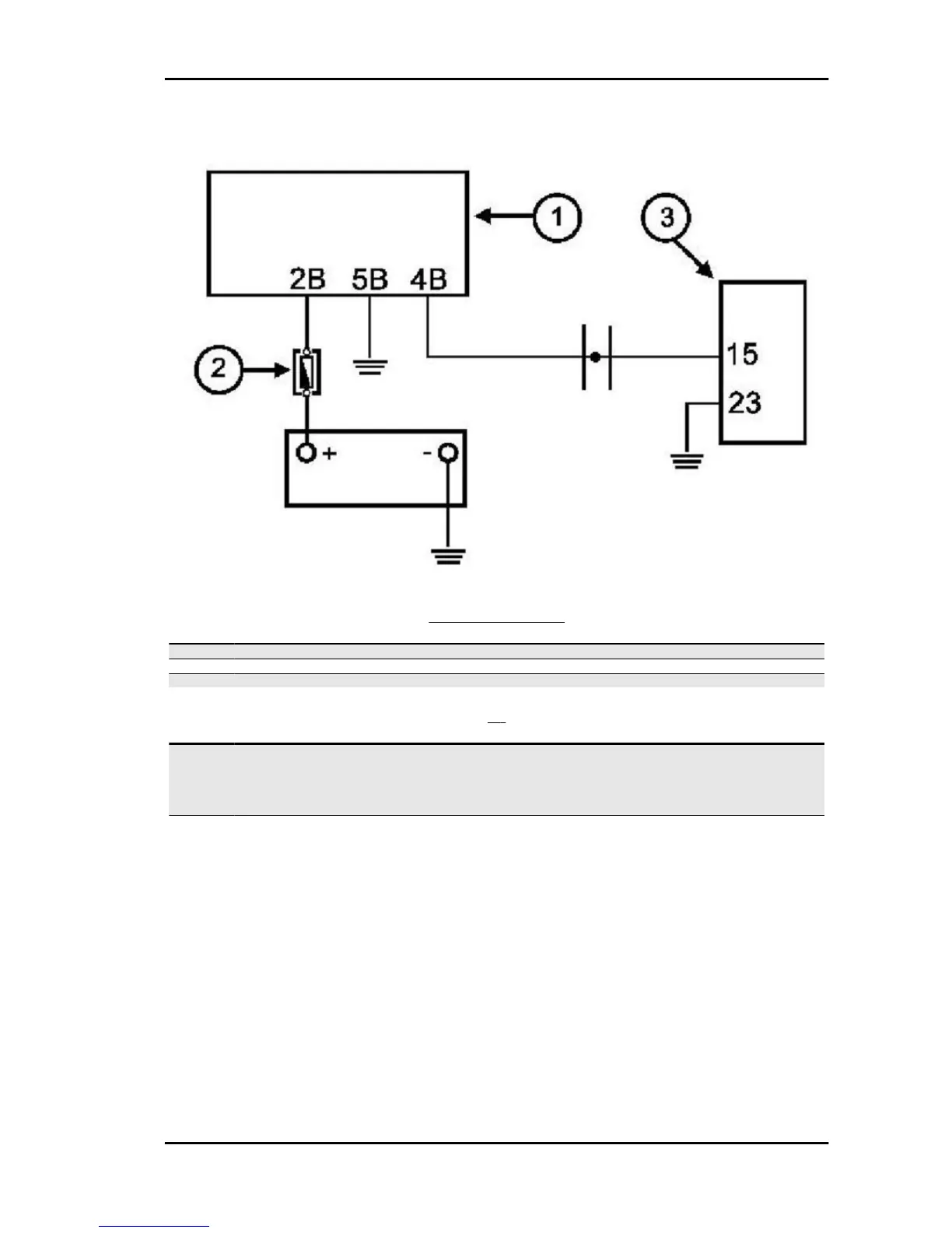
Injection warning light circuit
CIRCUIT LAYOUT
Specification
Desc./Quantity
1 Instrument panel
2 Fuse 7.5 A
3 Electronic control unit
[P]
Specification
Desc./Quantity
1 TERMINAL: 15 - 23 CONDITIONS: DURING THE CHECK
- Switch set to "ON"
- Side stand raised
- Switch to "RUN"
STANDARD VALUES : O V
2 TERMINAL: 15 - 23 CONDITIONS: AFTER THE CHECK
- Switch set to "ON"
- Side stand raised
- Switch to "RUN"
STANDARD VALUES : Battery voltage
The injection telltale light is controlled upon every switching to "ON" by the 3-second timing generated
by the digital instrument. This step is normally interrupted by the injection control unit control. The timing
lasts 5 seconds.
The diagnostic tester is not programmed to check this circuit.
Proceed as follows:
Specific tooling
020680Y Diagnosis Tool
1 - Turn the switch to the "ON" position Turn the emergency switch to position "RUN". Keep the side
stand raised. Make sure the light goes on for 5 seconds.
Beverly 500 i.e. Injection
INJEC - 187