[P]
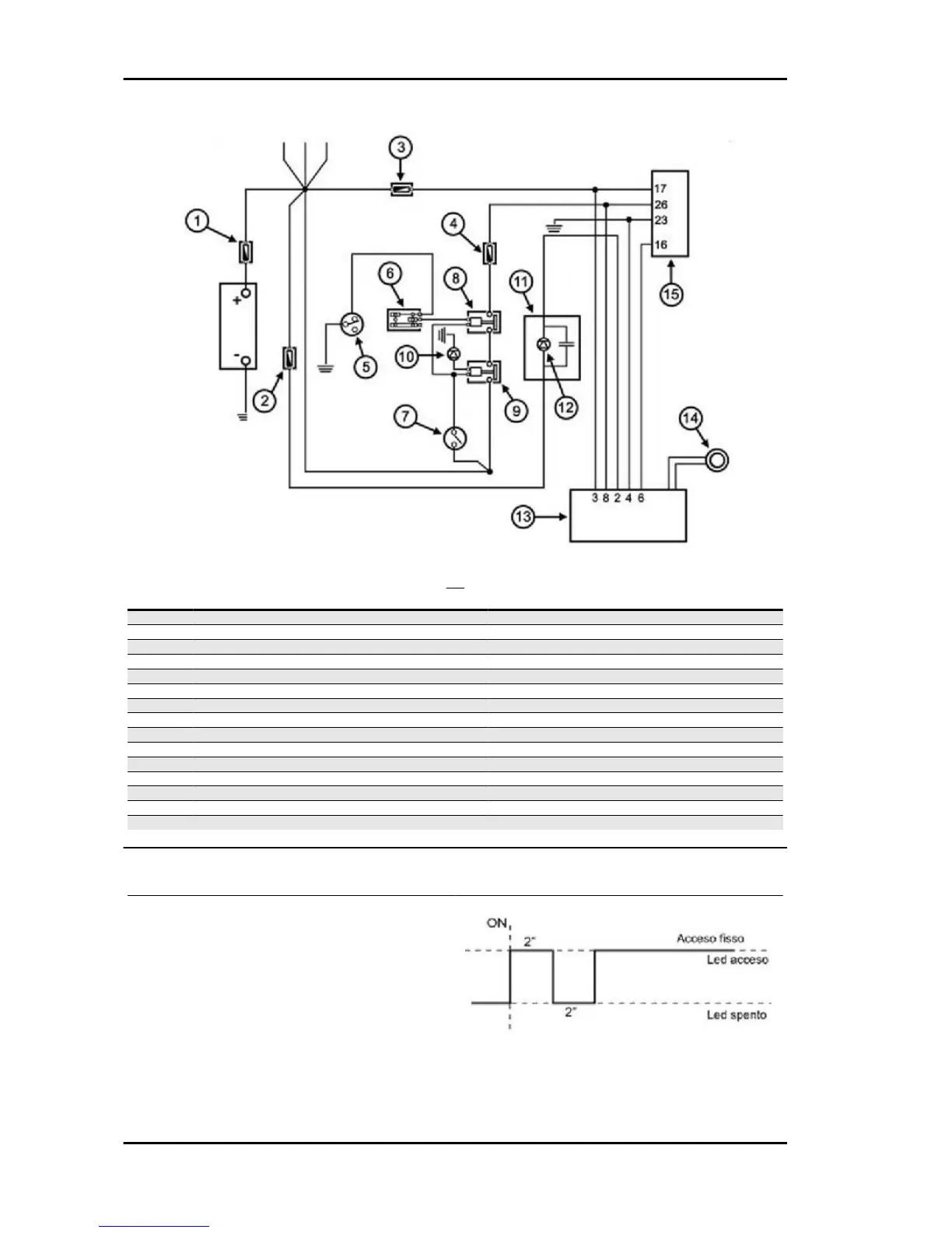
Specification
Desc./Quantity
1 Main fuse 30 A
2 Fuse 7.5 A
3 Fuse 3 A
4 Fuse 5A
5 Stand switch
6 Emergency switch
7 Key switch
8 Engine stop remote control switch
9 Main remote control switch
10 Diode 2 A
11 Instrument panel
12 Immobilizer LED
13 Decoder
14 Immobilizer aerial
15 Electronic control unit ECU
Virgin circuit
When control unit (ECU) and decoder are not pro-
grammed, the following conditions occur:
- Key switch set to "OFF". Deterrent flashing inac-
tive.
- Key switch set to "ON". Ignition and injection dis-
abled and LED on with solid light.
When the key switch is set to "ON", the LED
switches on as shown in the figure.
Injection Beverly 500 i.e.
INJEC - 216