9 - Replace the remote control switch
YES go to 8
10 - Connect the special tool between the control
unit and the system. Do not connect the electronic
control unit
YES go to 11
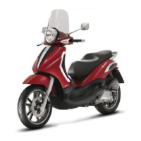
11 - Check for positive battery voltage at pin 85 of
the remote control switch connector.
85 (blue/grey) - 23 = Battery voltage with switch in
position "ON"
YES go to 13 NO go to12
12 - Repair or replace the wiring.
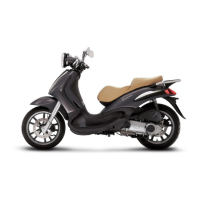
13 - Leaving the remote control switch disconnec-
ted, check for continuity between pin 86 of the
remote control switch connector and pin 5 of the
electronic control unit.
86 (green/white) - 5 = 0Ω (continuity)
YES go to 14 NO go to15
14 - Check the earth insulation.
5 - 23 >1 MΩ (infinite)
YES go to 16 NO go to 15
15 - Repair or replace the cable harness.
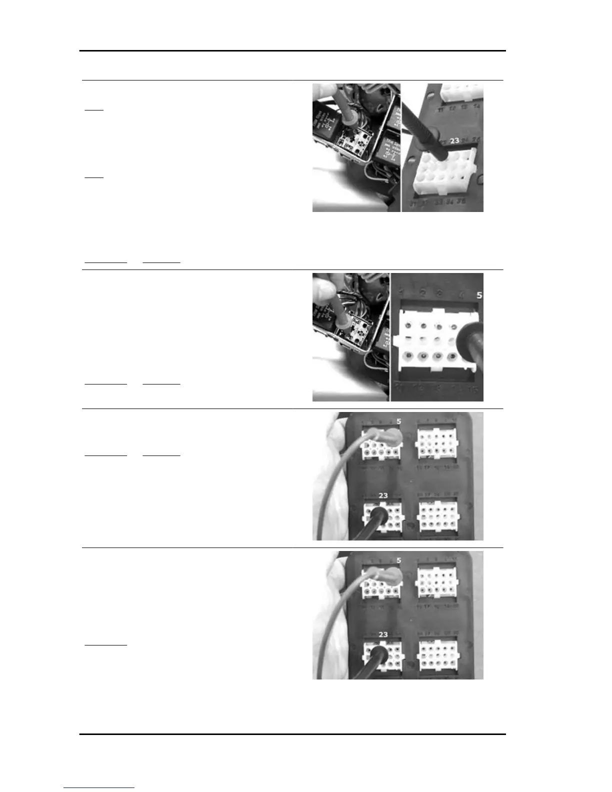
16 - Connect the remote control switch and check
for battery voltage between terminals 5 and 23 with
the key switch in position "ON".
5 - 23 = Battery voltage with panel in position "ON"
YES go to 17
17 - Repeat the check with the electronic control unit connected and the engine cold.
5 - 23 = Battery voltage with panel in position "ON"
Injection Beverly 500 i.e.
INJEC - 166