19 - Disconnect the following connectors: fuel
pump, H.V. coil, injector
YES go to 22
20 - Check the efficiency of the pump remote con-
trol switch. Check the wiring continuity between
remote control switch and pump.
87 (remote control switch) - green/black (pump) =
continuity
NO go to 21
21 - Fix the wiring and repeat the check from the
beginning.
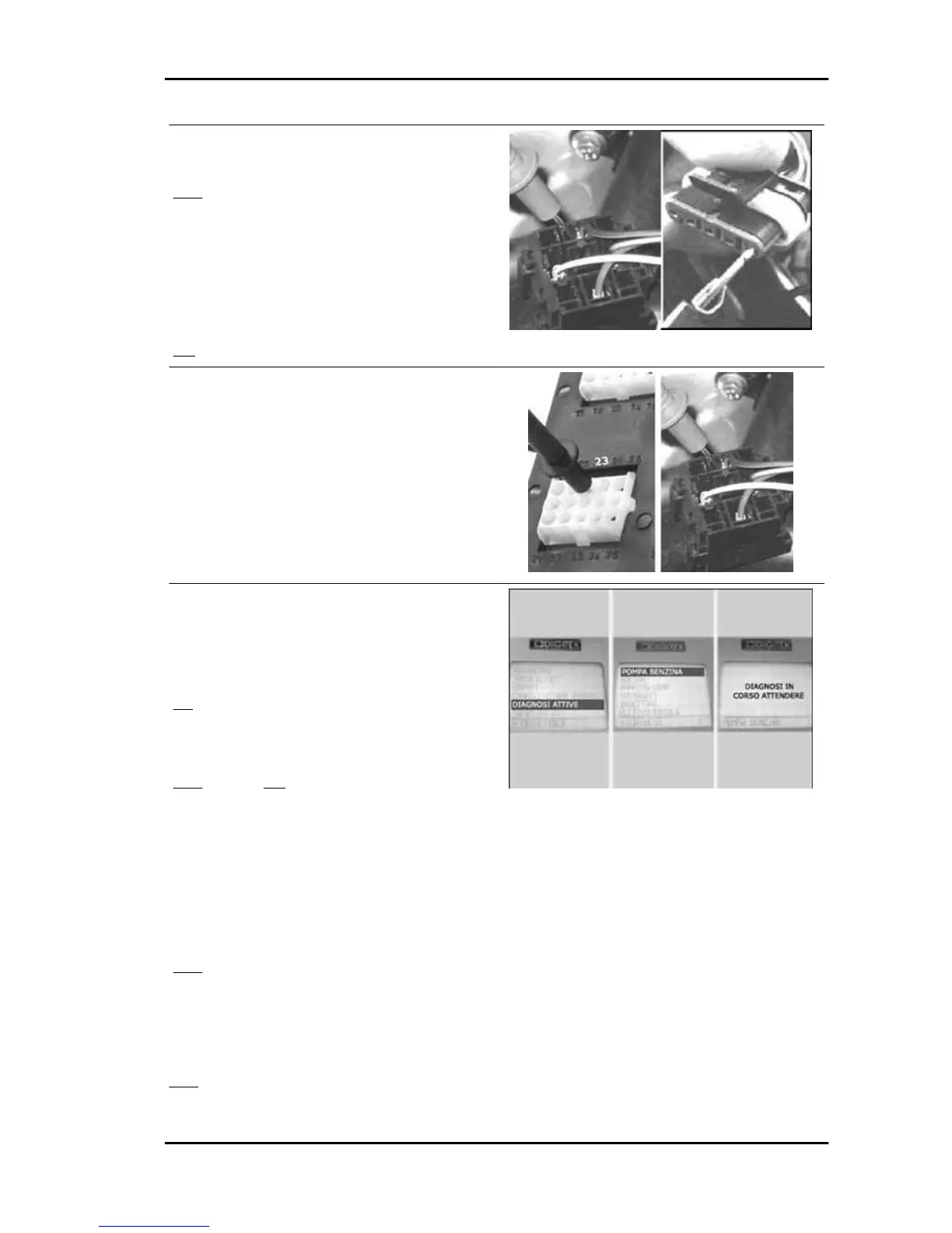
22 - Check the earth insulation of wiring
87 (pump remote control switch) - 23 = insulation
(>1 MΩ)
YES go to 24 NO go to 23
23 - Restore the wiring insulation and replace the
fuse.
24 - Check the ground insulation of the primary
winding of the HV coil and of the injector coil.
YES, go to 25
25 - Check the pump winding resistance: approx.
1.5Ω
YES go to 26 NO go to 27
26 - Replace the fuse and check the pump.
27 - Check the absorbed current.
28 - Select the diagnostic tester menu on the "AC-
TIVE DIAGNOSIS" function. Select the fuel pump
simulation function. Enable the function with con-
tinuous power supply on and engine off.
YES go to 29
Specific tooling
020680Y Diagnosis Tool
29 - The tester prompts the control unit to start the pump for 30 seconds
YES go to 30
30 - Acoustically check the following conditions:
Beverly 500 i.e. Injection
INJEC - 197