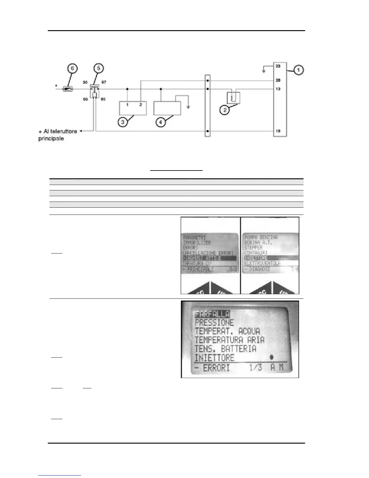
CIRCUIT LAYOUT
Specification Desc./Quantity
1 Electronic control unit
2 Injector
3 HV coil
4 Pump
5 Control unit remote control switch
6 Fuse 10 A
1 - Connect the diagnostic tester. Select the menu
on the "ACTIVE DIAGNOSIS" function.
Select the "INJECTOR" function.
YES go to 2
Specific tooling
020680Y Diagnosis Tool
2 - Enable the function with continuous power sup-
ply on and engine off. The control unit controls the
fuel pump continuously and at the same time starts
the injector opening. The injector openings are re-
peated for a few seconds.
YES go to 3
3 - Acoustically check the injector openings and
wait for the tester results
YES go to 4 NO go to 5
4 - 5 injector openings detected. The injection test-
er displays «test successful».
YES go to 7
Injection Beverly 500 i.e.
INJEC - 210