CIRCUIT LAYOUT
Specification Desc./Quantity
1 Electronic control unit
2 Injector
3 HV coil
4 Pump
5 Control unit remote control switch
6 Fuse 10 A
The ignition system is integrated with the injection
and it is a high-efficiency inductive type ignition.
The control unit manages two important parame-
ters:
- Ignition advance
This is optimised according to the engine rpm, to
the engine load, temperature and ambient pres-
sure
With idle engine, it is optimised to obtain the sta-
bilisation of the speed at 1450 ± 50 R/1'. - Mag-
netisation time
The coil magnetisation time is controlled by the
control unit. The ignition power is increased during
the engine start-up.
The injection system recognises the 4-stroke cycle
and therefore, ignition is only controlled during
compression.
To check the ignition circuit, proceed as follows:
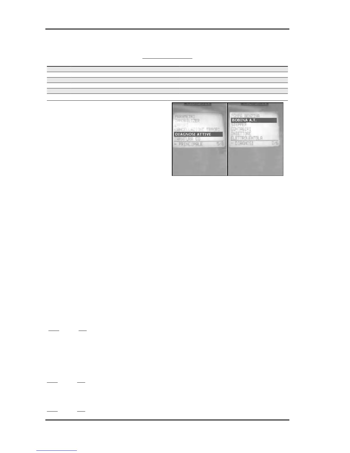
1 - Connect the diagnostic tester. Select the menu
on the "ACTIVE DIAGNOSIS" function. Start the
HV coil check with switch set to «ON», switch to
«RUN» and side stand raised. Wait for the tester
to display: "TEST SUCCESSFUL"
YES go to 3 NO go to 2
Specific tooling
020680Y Diagnosis Tool
2 - The tester displays: "TEST FAILED". Repeat the test and wait for the tester to display: "TEST SUC-
CESSFUL"
YES go to 3 NO go to 4
3 - Select the menu on the "ERRORS" function. Check the presence of current or stored errors relating
to the H.V. coil.
YES go to 6 NO go to 5
Injection Beverly 500 i.e.
INJEC - 230