020680Y Diagnosis Tool
2 - The EMS system has received no indications of temperatures out of the range of possible temper-
atures.
If you suspect a wrong temperature indication, proceed to perform the following check.
N.B.
A WRONG TEMPERATURE SIGNAL CAN BE DETECTED BY COUPLING THE ANALOGUE IN-
STRUMENT INDICATION WITH THE ELECTRIC FAN START.
IN ANY CASE, BEFORE CHECKING THE SENSOR, CHECK THE FILLING AND BLEEDING OF
THE COOLING SYSTEM
3 - Before checking the sensor and the relevant circuit, wait until the engine has cooled down and the
scooter has set to the working area temperature.
YES go to 4
4 - Set the switch to "ON" with switch to "RUN" and side stand raised. Select the menu on the "param-
eters" function. Do not start the engine.
YES go to 5
5 - Check the following values: coolant temperature intake air temperature ambient temperature The
three indications are equal or they are slightly different (e.g. 1° C).
YES go to 6 NO go to 7
6 - The temperature sensor is providing probably correct information.
Check at approx. 80° C.
7 - Install the special tool.
WARNING
DO NOT CONNECT THE CONTROL UNIT CONNECTOR.
Specific tooling
020481Y Control unit interface wiring
YES go to 8
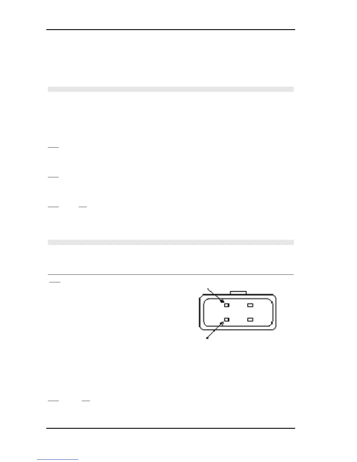
8 - Disconnect the coolant temperature sensor
connector. Measure the sensor resistance be-
tween the terminals shown in the figure.
Check that the resistance matches the values de-
clared according to the temperature.
Electric characteristic
TEMPERATURE RESISTANCE
9.6KW -10° C
5.975KW. 0
3.81KW +10° C .
2.5KW +20° C
1.68KW +30° C
0.3KW +80° C
YES go to 10 NO go to 9
9 - Replace the sensor.
10 - Connect the sensor connector and repeat the resistive check at terminals 4 and 22;
Injection Beverly 500 i.e.
INJEC - 238