STANDARD: 5 V
TERMINALS: 11 - 22
CONDITIONS: Opening the throttle gradually
STANDARD: Volt= Progressive increase
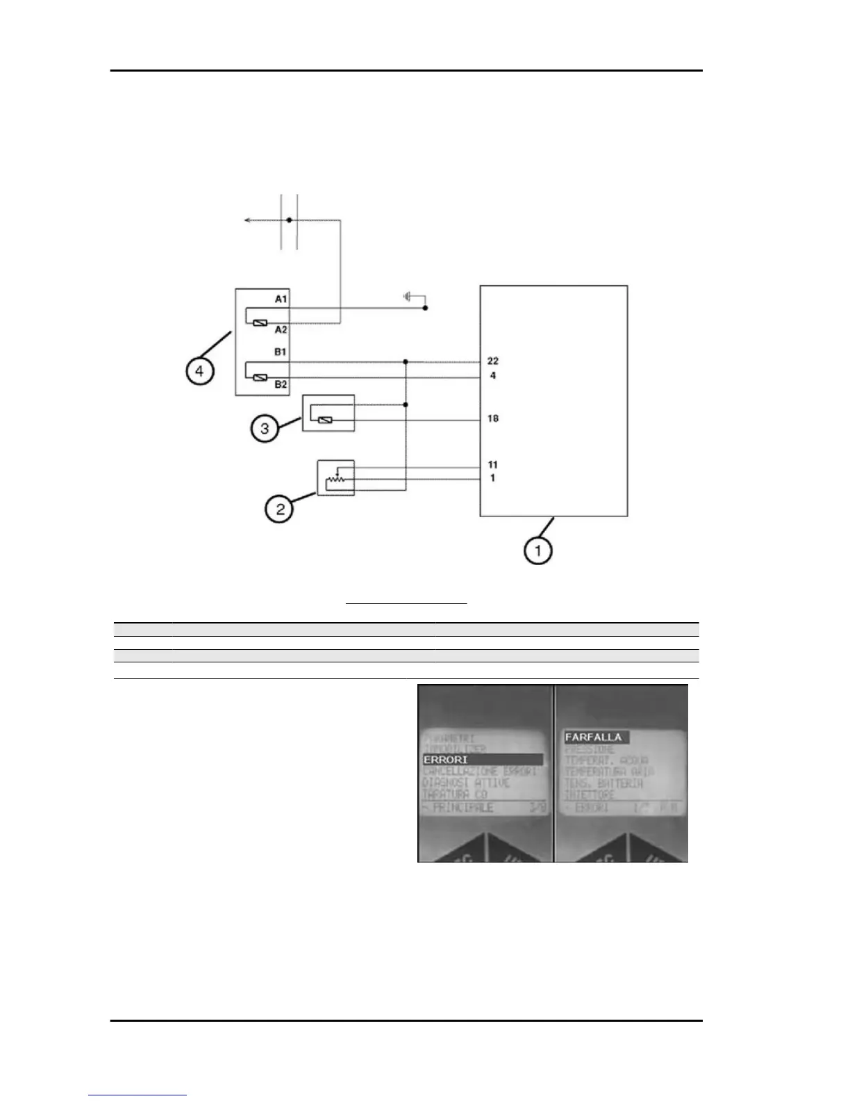
CIRCUIT LAYOUT
Specification
Desc./Quantity
1 Electronic control unit
2 Valve position sensor
3 Air temperature sensor
4 Fluid temperature sensor
The throttle valve position sensor is not removable
and is installed on the throttle body.
This sensor receives a 5-V power supply from the
control unit and transmit a gradually increasing
voltage to the same, with an increase of the throttle
valve opening. The control unit converts this volt-
age at an angular position of the valve.
The engine rpm and the throttle valve position are
the two basic signals for the engine management.
A failure of this circuit causes the switching on of
the injection telltale light and the tripping of the
safeties. In these conditions, the engine works,
Injection Beverly 500 i.e.
INJEC - 248