16 - MCM260X - Manuale d’uso
4.1.c MCM260X-5AD
1
–
12..24 VAC / VDC
2
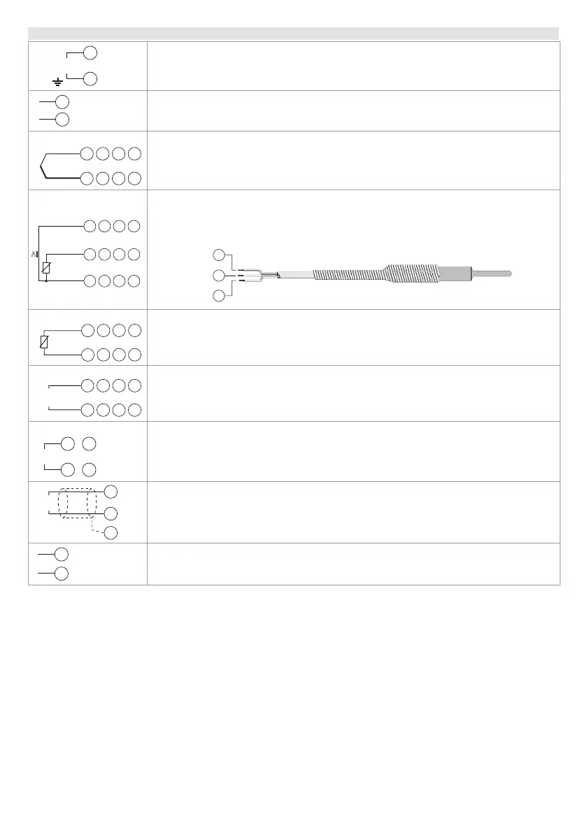
Power supply 12..24Vac/dc ±15%
1: +Vdc
2: -Vdc
3
4
+V
Power supply for normalized sensors
AI1
+
AI
TC
6
5
AI2
9
8
AI3
19
18
AI4
22
21
Analog inputs for thermocouples K, S, R, J, T, E, N, B.
• Respect the polarity
• To avoid extensions use a compensating cable and clips that suit the
thermocouple used (compensating)
AI1 AI2 AI3 AI4
AI
Rosso
Red
Bianco
White
Rosso
Red
PT/NI100
7
5
6
10
8
9
20
18
19
23
21
22
Analog inputs for resistance thermometers PT100, Ni100.
• For the three wire connection use cables with the same section
• For the two wire connection short circuit clips 6 and 7 (AI1), 9 and 10 (AI2),
19 and 20 (AI3), 22 and 23 (AI4).
RED
ROSSO
RED
ROSSO
WHITE
BIANCO
5
7
6
10
8
20
18
23
21
AI
PTC/NTC
7
5
Analog inputs for resistance thermometers NTC, PTC, PT500, PT1000 and
linear potentiometers.
+
–
AI
V
mA
6
5
9
8
19
18
22
21
Analog inputs for normalized current and voltage signals.
• Respect the polarity.
11
+
–
V / mA
12
24
25
Analog outputs AO1 and AO2
CAN
RS485
CANL (A)
(C)
Shield / Schermo
14
13
15
Field bus:
13: CANH / (B) RS485+
14: CANL / (A) RS485-
15: (C) GND for CANbus and Modbus RTU
16
I-ID
17
Automatic routing terminals (Modbus RTU only)
16: Automatic routing output
17: Automatic routing input