User’s Manual
The scenario is described as follows:
Untagged packet entering VLAN 2
1. While [PC-1] transmit an untagged packet enters Port-1, the Industrial Managed Switch will tag it with a VLAN
Tag=2. [PC-2] and [PC-3] will received the packet through Port-2 and Port-3.
2. [PC-4],[PC-5] and [PC-6] received no packet.
3. While the packet leaves Port-2, it will be stripped away it tag becoming an untagged packet.
4. While the packet leaves Port-3, it will keep as a tagged packet with VLAN Tag=2.
Tagged packet entering VLAN 2
5. While [PC-3] transmit a tagged packet with VLAN Tag=2 enters Port-3, [PC-1] and [PC-2] will received the packet
through Port-1 and Port-2.
6. While the packet leaves Port-1 and Port-2, it will be stripped away it tag becoming an untagged packet.
Untagged packet entering VLAN 3
1. While [PC-4] transmit an untagged packet enters Port-4, the switch will tag it with a VLAN Tag=3. [PC-5] and
[PC-6] will received the packet through Port-5 and Port-6.
2. While the packet leaves Port-5, it will be stripped away it tag becoming an untagged packet.
3. While the packet leaves Port-6, it will keep as a tagged packet with VLAN Tag=3.
For this example, just set
VLAN Group 1 as default VLAN, but only focus on VLAN 2 and VLAN 3
traffic flows
Setup steps
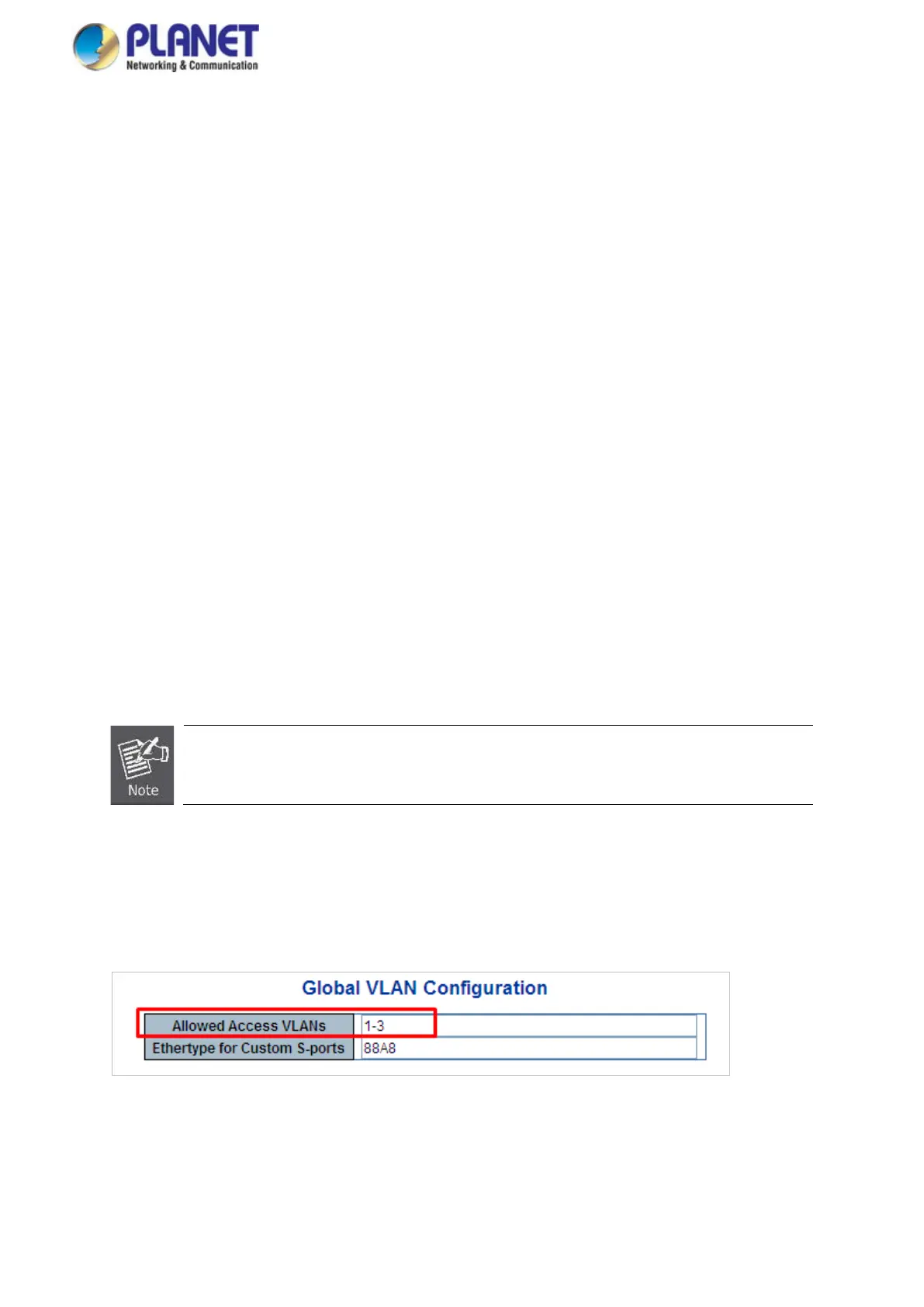
1. Add VLAN Group
Add two VLANs – VLAN 2 and VLAN 3
For Type 1-3 in Allowed Access VLANs column, the 1-3 includes VLAN1 and 2 and 3.
Figure 4-6-9: Add VLAN 2 and VLAN 3
 Loading...