User’s Manual
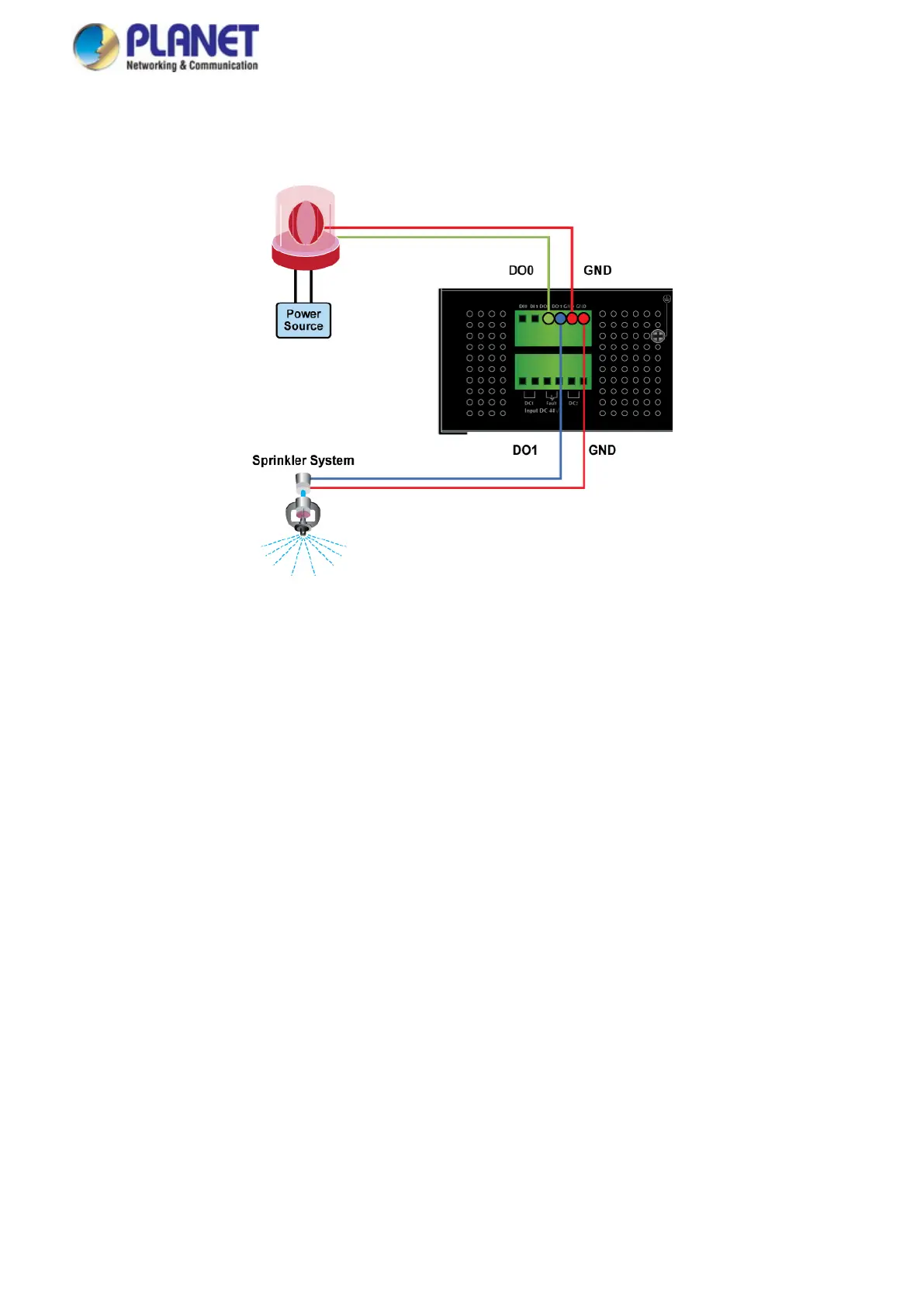
4. There are two Digital Output groups for you to sense IGS-10020PT/10020HPT/12040MT/20040MT/20160HPT port failure
or power failure and issue a high or low signal to external device. The following topology shows how to wire DO0 and
DO1.
Figure 2-24 Wires DO0 and DO1 to Open Detector
2.2 Installing the Industrial Managed Switch
This section describes how to install your Industrial Managed Switch and make connections to the Industrial Managed
Switch. Please read the following topics and perform the procedures in the order being presented. To install your Industrial
Managed Switch on a desktop or shelf, simply complete the following steps.
In this paragraph, we will describe how to install the Industrial Managed Switch and the installation points attended to it.
2.2.1 Installation Steps
1. Unpack the Industrial Managed Switch
2. Check if the DIN-Rail is screwed on the Industrial Managed Switch or not. If the DIN-Rail is not screwed on the
Industrial Managed Switch, please refer to DIN-rail Mounting section for DIN-rail installation. If users want to
wall-mount the Industrial Managed Switch, please refer to the Wall Mount Plate Mounting section for wall-mount plate
installation.
3. To hang the Industrial Managed Switch on the DIN-rail track or wall.
4. Power on the Industrial Managed Switch. Please refer to the Wiring the Power Inputs section for knowing the
information about how to wire the power. The power LED on the Industrial Managed Switch will light up. Please refer to
the LED Indicators section for indication of LED lights.
5. Prepare the twisted-pair, straight-through Category 5 cable for Ethernet connection.
 Loading...