User’s Manual
2.1.5 Wiring the Fault Alarm Contact
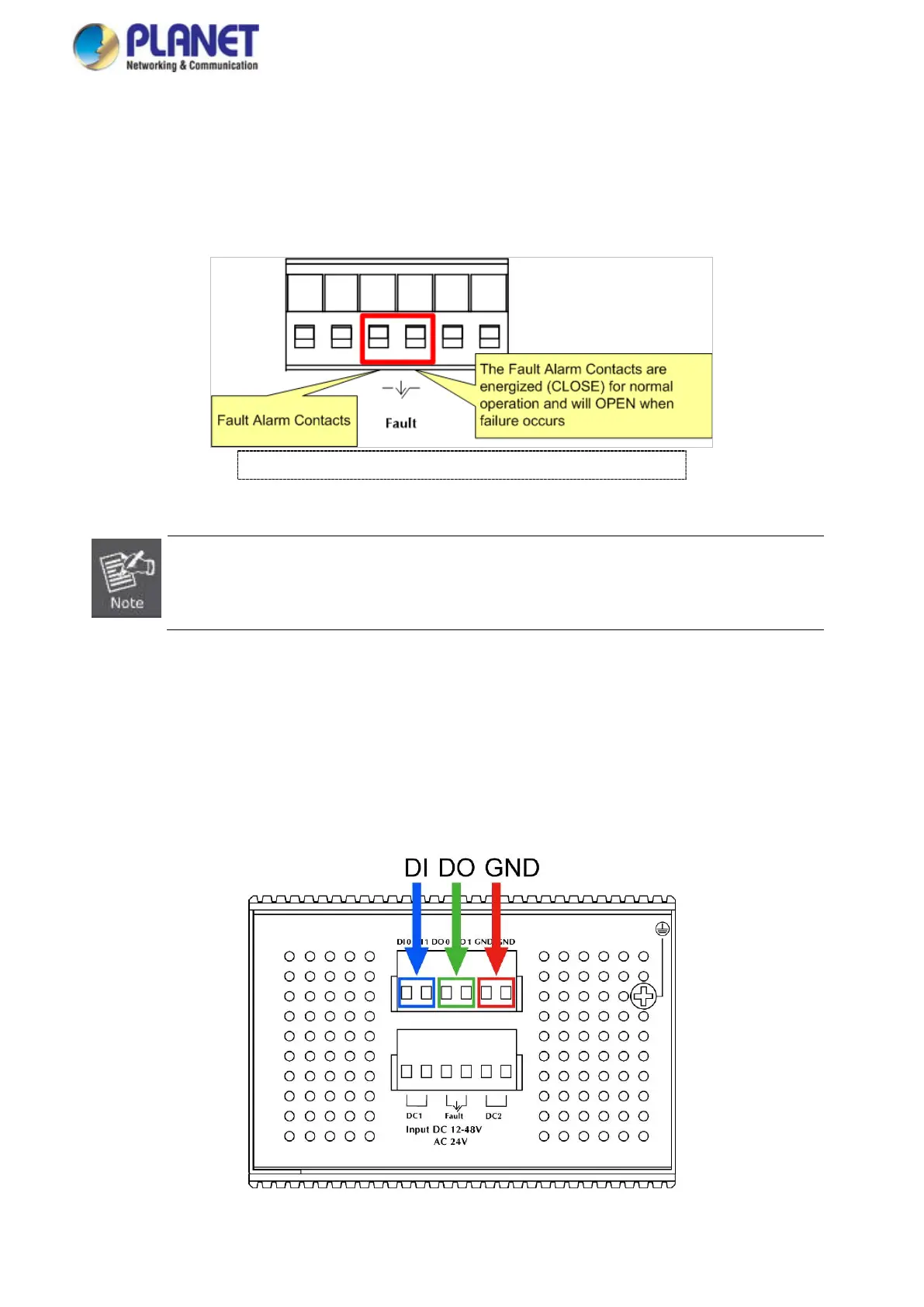
The fault alarm contacts are in the middle (3 & 4) of the terminal block connector as the picture shows below. Inserting the wires,
the Industrial Managed Switch will detect the fault status of the power failure, or port link failure (available for managed model).
The following illustration shows an application example for wiring the fault alarm contacts
Insert the wires into the fault alarm contacts
1. The wire gauge for the terminal block should be in the range of 12 ~ 24 AWG.
2. When performing any of the procedures like inserting the wires or tightening the wire-clamp screws,
make sure the power is OFF to prevent from getting an electric shock.
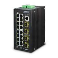
2.1.6 Wiring the Digital Input/Output
The 6-contact terminal block connector on the rear panel of IGS Series is used for Digital Input and Digital Output. Please follow
the steps below to insert wire.
1. The IGS-10020PT/10020HPT/12040MT/20040MT offers two DI and DO groups. 1 and 2 are DI groups; 3 and 4 are DO
groups; and 5 and 6 are GND (ground).
Figure 2-21 Wiring the Redundant Power Inputs
 Loading...