User’s Manual
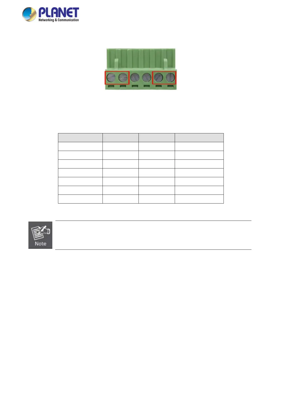
2. Tighten the wire-clamp screws for preventing the wires from loosening.
Figure 2-20 6-Pi n Te rminal Block Power Wiring Input
Model Name Positive (+) Pin Negative (-) Pin Input Voltage
IGS-10020MT Pin 2/6 Pin 1/5 DC 12~48V, AC 24V
IGS-10020PT/HPT Pin 1/6 Pin 2/5 DC 48V
IGS-10020HPT Pin 1/5 Pin 2/6 DC 48V
IGS-10080MFT Pin 1/5 Pin 2/6 DC 12~48V, AC 24V
IGS-12040MT Pin 1/5 Pin 2/6 DC 12~72V, AC 24V
IGS-20040MT Pin 1/5 Pin 2/6 DC 9~48V, AC 24V
IGS-20160HPT Pin 1/5 Pin 2/6 DC 48~56V, AC 24V
1. The wire gauge for the terminal block should be in the range of 12 ~ 22 AW G@25 degrees C.
2. When performing any of the procedures like inserting the wires or tightening the wire-clamp screws,
make sure the power is OFF to prevent from getting an electric shock.
 Loading...