User’s Manual
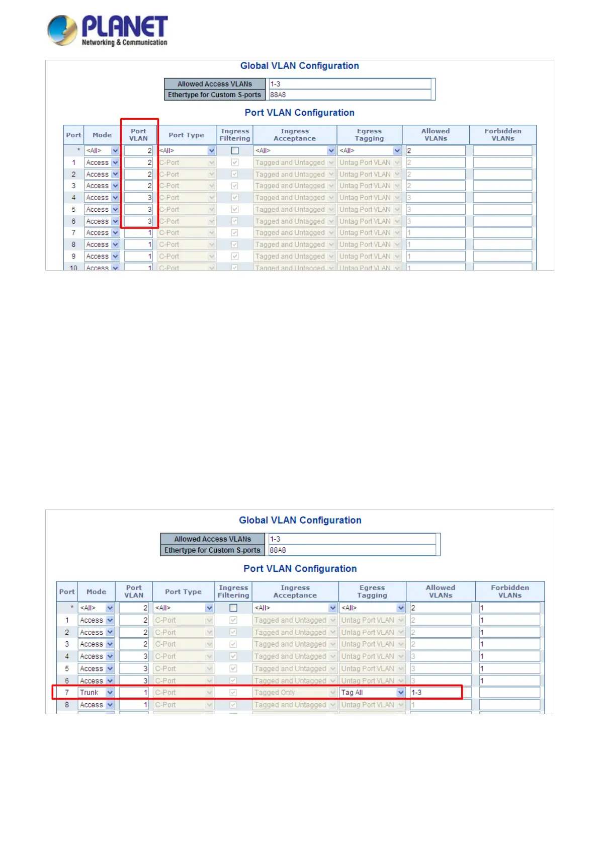
Figure 4-6-14: Changes Port VLAN of Port 1~3 to be VLAN2 and Port VLAN of Port 4~6 to be VLAN3
For the VLAN ports connecting to the hosts, please refer to 4.6.10.1. The following steps focus on the VLAN Trunk port
configuration.
1. Specify Port-7 to be the 802.1Q VLAN Trunk port.
2. Assign Port-7 to both VLAN 2 and VLAN 3 on the VLAN Member configuration page.
3. Define a VLAN 1 as a “Public Area” that overlaps both VLAN 2 and VLAN 3 members.
4. Assign the VLAN Trunk Port to be the member of each VLAN to be aggregated. For this example, add Port-7 to be VLAN 2
and VLAN 3 member port.
5. Specify Port-7 to be the 802.1Q VLAN Trunk port, and the Trunk port must be a Tagged port while egress. The Port-7
configuration is shown in Figure 4-6-15.
Figure 4-6-15: VLAN Overlapping Port Setting & VLAN 1 – The Public Area Member Assigned
VLAN 2 members of Port-1 to Port-3 and VLAN 3 members of Port-4 to Port-6 also belong to VLAN 1. But with different PVID
settings, packets from VLAN 2 or VLAN 3 are not able to access to the other VLAN.
 Loading...