7088-8000
-159
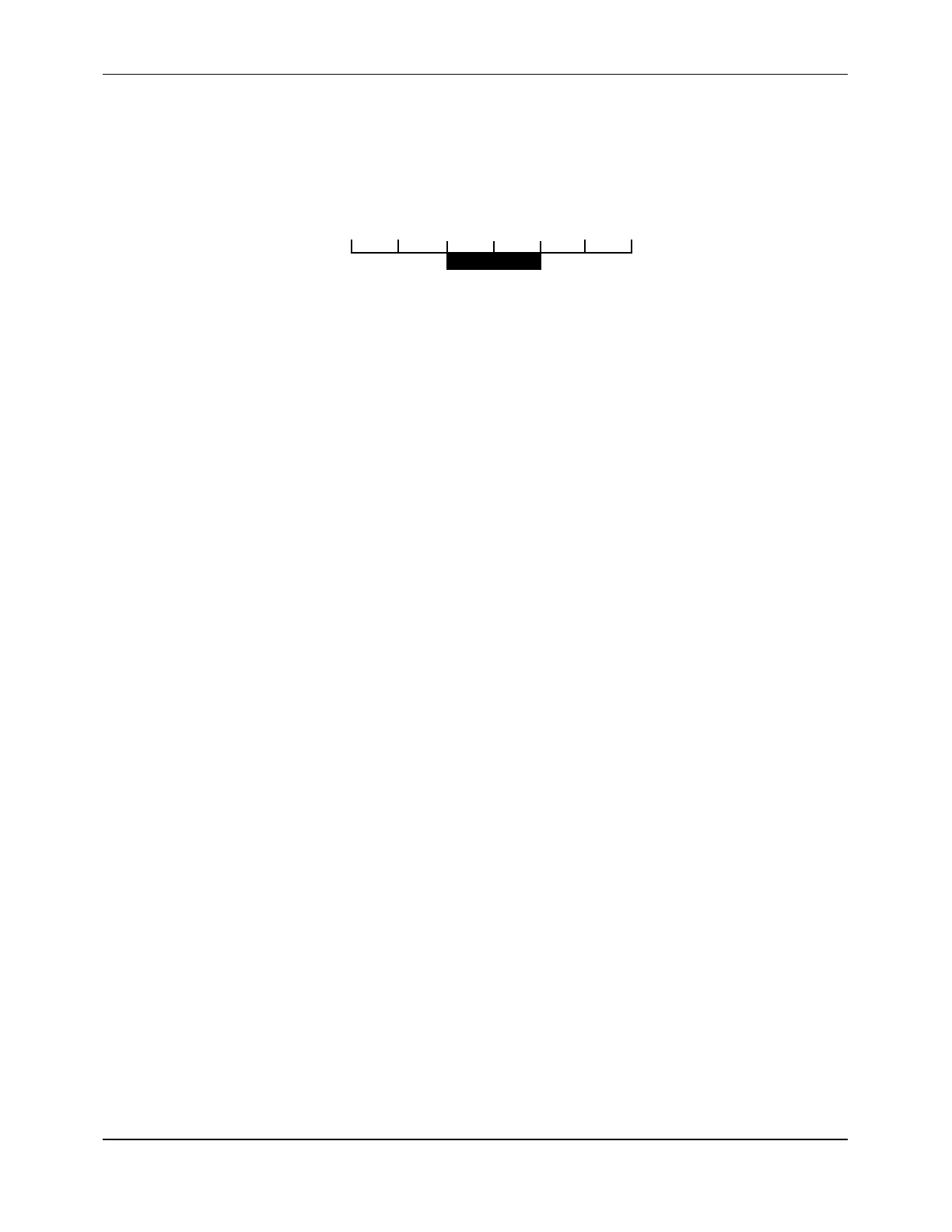
For example, if a low flow cutoff of 0.1 feet per second (.03 meters per second) is entered,
the instrument would be driven to zero for flow rates less than 0.1 foot per second in the
positive direction and greater than -0.1 foot in the negative direction (Figure F-17).
-0.3 -0.2 -0.1 0 +0.1 +0.2 +0.3
Zero flow
displayed here
Figure F-17 Low Flow Cutoff (example)
To set the low flow cutoff:
1. From the
FLOW
options group, click on the
LOW FLOW CUTOFF
text box.
2. Enter the value for the low flow cutoff.
NOTE:
The value for the low flow cutoff should be set as high as is practical to
maximize the stability of the zero flow setting.
Low Signal Cutoff
Empty pipes or solids, bubbles, or voids in the flow stream may cause temporary drops in
signal strength and erroneous readings. The effect of these dropouts can be minimized by
setting a low signal cutoff. Setting a low signal cutoff (a minimum acceptable signal
amplitude), drives the flowmeter to the loss-of-signal (LOS) condition. The flowmeter’s
response to the LOS condition may be programmed as follows:
!
Drop the reading to zero
!
Hold the last valid reading (but continue to totalize)
In addition to these two options, a relay can be actuated based on the low signal cutoff
(Section F.4.9).
To set the low signal cutoff:
1. From the
FLOW
options group, click on the
LOW SIGNAL CUTOFF
text box.
2. Enter the value for the low signal cutoff.
NOTE:
The value for the low signal cutoff should typically be set at approximately
one-half of the value of the signal strength present under flow conditions.
Note that signal strength is typically not significantly affected by flow rate.
3. Click on one of the following radio buttons:
!
ZERO
(to drop the reading to zero during an LOS condition)
!
HOLD
(to hold the last valid reading during an LOS condition)