Appendix C
A-63
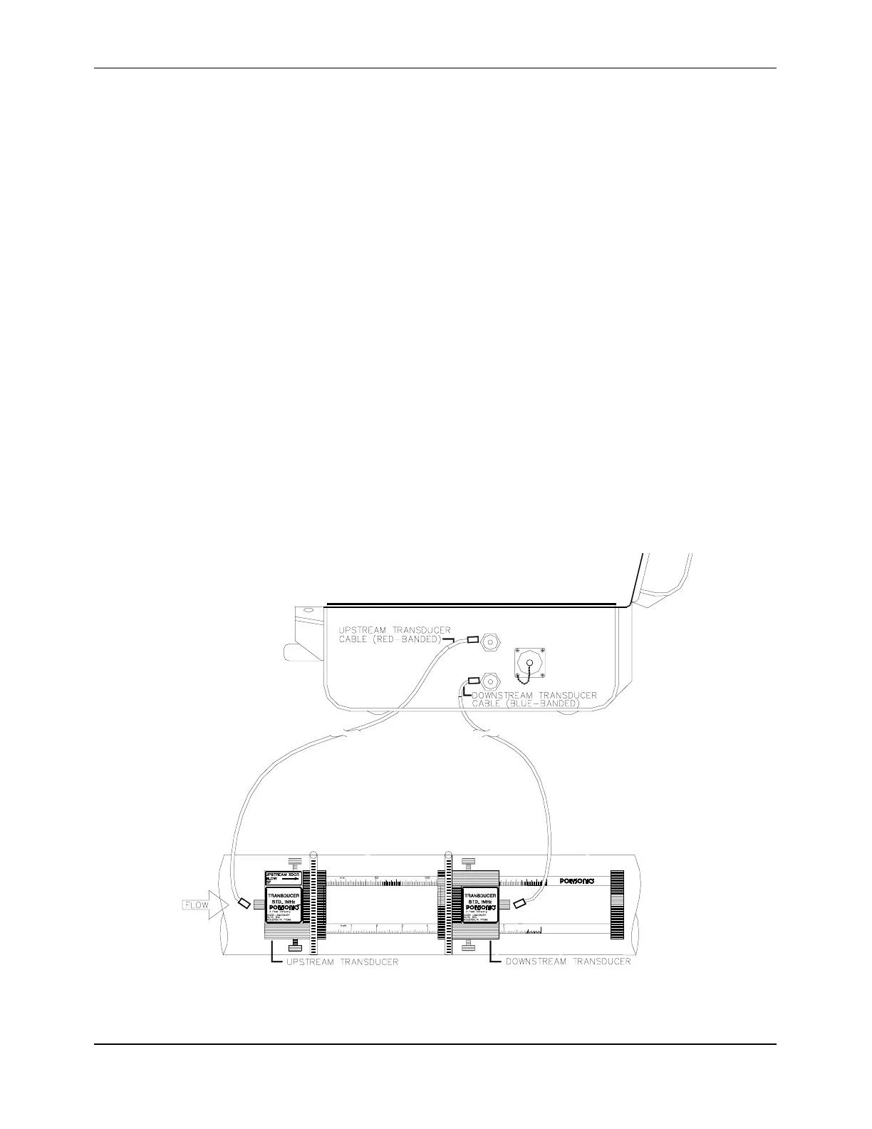
The flowmeter has two transducer cables: the upstream transducer cable, which has
red-banded ends and the downstream transducer cable which has blue-banded ends.
There are two BNC connectors for the transducer cables on the right side of the
flowmeter. The upstream connector is in the uppermost position and the downstream
connector is in the lower position when the case is opened (Figure 4-2). Reversing the
cables on either the instrument or transducer ends will result in flow measurement in
the reverse direction of actual flow.
8. Connect the transducer cables.
9. Calibrate the flowmeter if maximum possible accuracy is important (Chapter 5).
10. Access Menu 00.
The flowmeter is now capable of accurately measuring velocity and flow.
4.2.1 USING THE SLIDE TRACK
The transducer slide track (Figure 4-2) comes standard with the DCT-7088. It may be used
for mounting transducers with the V or W mounting method, but cannot be used for the Z
method. It is limited to pipe sizes with outer diameters of 1 to approximately 16 inches (25
to 406 millimeters). Although not required, the slide track is convenient for mounting the
transducers since it has spacing measurements printed on its two rails. The top rail is
marked off in inches (in 0.1 and 0.05 increments) and the bottom rail is marked off in
millimeters.
Figure 4-2 Using the Slide Track