7088-8000
-8
PRODUCT OVERVIEW
1.1 Introduction
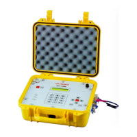
The DCT-7088 Digital Correlation Transit Time Flowmeter is a member of the Polysonics
series of Tyme Flyte ultrasonic instruments. This microprocessor-based instrument is used
to measure the flow of clean, homogeneous liquids (liquids without large concentrations of
suspended particles or gasses such as air bubbles.) The flowmeter is non-invasive, which
means that it measures flow from outside the pipe. Its transducers can be mounted to a pipe
within a matter of minutes, and flow measurements may be made without stopping the
flow or physically contacting it in any way.
The flowmeter is configured using an integrated keypad and display for entering variables
such as pipe size, material, wall thickness, and fluid type (Chapter 3). The flowmeter
displays the flow rate and the totalized volume is either English or metric engineering
units. In addition, it can be remotely configured and monitored via the RS232 interface
mode using the PolyLink flowmeter data link utility (Appendix A). Alternatively, the
flowmeter can be configured and the signal can be graphically analyzed in a Microsoft
Windows
®
environment using the Polysonics
TimeGATE
™
utility (Appendix F).
1.2 Theory of Operation
Sound waves travel in fluids at a specific velocity depending on the type of fluid. If the
fluid is moving, the sound wave travels at a velocity equal to the sum of the speed of sound
in the fluid and the velocity of the fluid itself. A sound wave traveling in the same
direction as the fluid flow (downstream) will arrive sooner than a sound wave traveling
against the flow (upstream). The DCT-7088 transit time flowmeter operates by measuring
the difference in time required for sound waves to travel between externally mounted
downstream and upstream transducers (Figure 1-1). Based on the transit time of the two
sound waves, the flowmeter calculates the average fluid velocity.
Several variables must be taken into consideration, however. The overall velocity of the
fluid is actually made up of many individual local velocities that vary according to their
distance from the pipe wall. The velocities in the center of the pipe are higher than the
velocities near the pipe wall. The combination of these individual velocities for a specific
type of fluid within a specific pipe yield a velocity distribution known as the flow profile
(Figure 1-2). By properly configuring the flowmeter, the effects of the flow profile are
taken into consideration when calculating the mean fluid velocity. The flowmeter then
multiplies this velocity by the pipe’s cross-sectional area to obtain volumetric flow.

 Loading...